Dealer Service 25
MAN0646 (Rev. 11/5/2007)
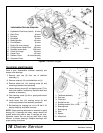
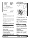
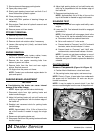
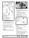
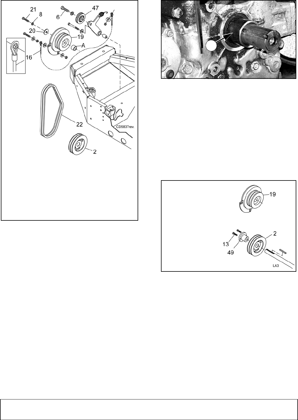
Figure 15. Clutch Assembly
3. Place a 9/16 wrench over cap screw (6) on idler
(47) and remove the tension from PTO V-belts (22)
by rotating the wrench clockwise.
4. Remove PTO V-belts (22) from PTO drive sheave
(2).
5. Disconnect electrical wire harness from clutch.
6. Disconnect clutch cable (16) from clutch.
7. Remove cap screw (21), lock washer (8) and
retaining washer (20) from end of clutch.
8. Remove clutch (19) and clutch spacer (A) from
engine shaft.
Install Clutch
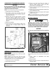
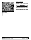
1. Install clutch spacer (A) over engine shaft with the
chamfer side towards the engine. See Figure 16.
Figure 16. Clutch Spacer Installed
2. Install clutch onto engine shaft.
3. Secure clutch to engine shaft using 3/8 NF cap
screw GR8 (21) and lock washer (8) previously
removed (Figure 15).
NOTE: Place a drop of Loctite
®
242 (blue) on
threads of cap screw before installing.
4. Torque Grade 8 cap screw (21) to 40 lbs-ft.
5. Check belt alignment and if necessary adjust PTO
sheave on shaft. See .
NOTE: If belt alignment is not necessary, proceed
to Reassemble Components.
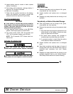
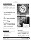
Figure 17. Align Clutch & PTO Sheave
Align Belt
6. Loosen the taper bolts (13), adjust sheave (2), and
tighten bolts to 85 lbs-inch.
Reassemble Components
1. Install PTO V-belts (22) over PTO sheave (2) and
clutch (19).
2. Attach clutch cable (16) to clutch (19) using
hardware previously removed. Make sure nut is
inside of loop of cable and between washers.
Cable must pivot freely, (see Figure 15).
3. Attach electrical wiring harness to clutch.
4. Replace counterweights if removed.
A. Clutch
spacer
2. PTO Sheave
6. 3/8 NC x 1-3/4 HHCS GR5
8. 3/8 Lock washer
16. Cable, clutch stop
19. Electric clutch, mag-stop 1-1/8
20. 13/32 x 1-1/2 Retaining washer
21. 3/8 NF x 1-1/4 HHCS GR8
22. PTO V-belt set, matched
A
DP10
2. PTO sheave
13. 1/4 NC x 3/4 HHCS
GR5
19. Electric clutch, mag-
stop 1-1/8
46. Taper lock


