


Dealer Service 21
MAN0646 (Rev. 11/5/2007)
DEALER SERVICE
The information in this section is written for dealer ser-
vice personnel. The repair described here requires
special skills and tools. If your shop is not properly
equipped or your mechanics are not properly trained in
this type of repair, you may be time and money ahead
to replace complete assemblies.
Before performing any service or maintenance,
lower attachment to ground, turn off power unit
engine, remove key, and disconnect battery ground
cable (negative -).
Keep all persons away from operator control
area while performing adjustments, service, or
maintenance.
Always wear relatively tight and belted clothing
to avoid getting caught in moving parts. Wear
sturdy, rough-soled work shoes and protective
equipment for eyes, hair, hands, hearing, and head;
and respirator or filter mask where appropriate.
TROUBLESHOOTING HYDROSTATIC
PUMP
Loss of Power in Transmission
1. Make sure transmission fluid is correct.
2. Make sure hydrostatic pump and fan blades are
clean.
NOTE: Overheating can cause loss of power or
fluid leaks from excess fluid expansion.
3. Make sure dump valves are tightened down.
NOTE: Transmission fluid can leak by the dump
valve if by-pass is not tight. Tighten hex head if
dump valves are loose.
No Positive Neutral Position
If drive wheels travel forward or reverse when steering
handles are in the NEUTRAL position (pivoted out-
ward), adjustment of hydrostatic pumps is necessary.
1. Block up power unit frame so both drive wheels are
off the ground.
2. Release parking brake.
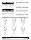
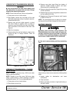
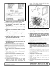
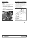
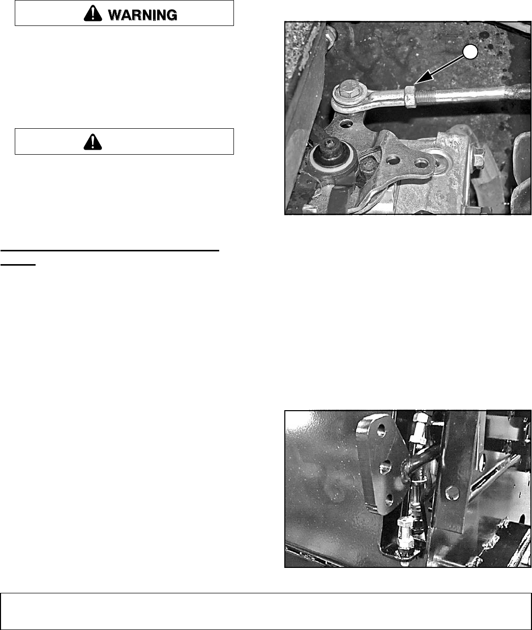
3. Loosen jam nut (1) on linkage rod as shown in
Figure 10.
4. Place steering handles in the NEUTRAL position
(pivoted outward) and start engine.
5. If drive wheels turn, turn rod out or in until wheel
stops.
6. Tighten jam nut.
7. Repeat steps 3 through 6 for other hydrostatic
pump control arm.
Figure 10. Jam Nut on Linkage Rod, Left Pump
Straight Line Travel Adjustment
1. Check tire pressure; tires must have equal air
pressure.
2. Check travel; drive forward with both steering
handles full forward at half throttle.
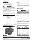
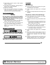
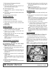
• If travel is not straight, adjust steering handle stop
bolt on opposite side of turn.
• If power unit turns to the left, raise steering stop
bolt on the right.
• If power unit turns to the right, raise steering stop
bolt on the left.
Figure 11. Left Side Steering Stop Bolts
CAUTION
1
DP4