24 Dealer Service
MAN0646 (Rev. 11/5/2007)
7. Start engine and disengage parking brake.
8. Open pump dump valve.
9. Slowly push steering levers back and forth 5 to 6
times to bleed the hydraulic system.
10. Close pump dump valve.
11. Adjust NEUTRAL position of steering linkage as
necessary.
12. Stop engine. Check level of hydraulic reservoir and
check for leaks.
13. Remove power unit from stands.
PTO BELT REMOVAL
1. Remove key from switch.
2. Remove belt shield, if necessary
3. Remove clutch anti-rotation cable, if necessary.
4. Loosen idler spring bolt (J-bolt), and derail belts
from pulleys.
5. Remove belts.
ENGINE REMOVAL
1. Disconnect throttle cable, battery cables, hoses,
fuel line, and electrical wires from engine.
2. Remove the four engine mounting bolts from
bottom of power unit frame.
3. Remove belts from the front and rear engine
pulleys. See belt removal.
4. Lift engine from the power unit frame.
NOTE: Contact your authorized engine dealer for
parts and repairs.
PARKING BRAKE ADJUSTMENT
NOTICE
■ Overtightening the brake can cause internal
damage to the brake linkage.
NOTE: Adjust right and left brakes individually.
1. Disconnect clevis from right parking brake and
brake handle linkages.
2. Adjust left parking brake pull rod until brake rock
shaft lug is perpendicular with the bottom edge of
the frame rail.
3. Readjust and reconnect clevis for parking brake
handle linkage.
NOTE: Approximately 12 to 13 lbs of force at the
top of the handle is needed to apply the single
brake.
4. Reconnect right parking brake rod.
5. Disconnect clevis from left parking brake and brake
handle linkages.
6. Adjust right parking brake pull rod until brake rock
shaft lug is perpendicular with the bottom edge of
the frame rail.
7. Reconnect parking brake rod.
NOTE: Approximately 24 to 26 lbs of force at the
top of the handle is needed to apply both brakes.
SOLENOID TEST
1. Disconnect solenoid from engine and briefly crank
engine.
2. Leave key ON. Fuel solenoid should be engaged
(pushed out).
NOTE: If fuel solenoid will not engage, check inline
fuse. If fuse is OK, test the solenoid in this manner:
a. Disconnect wires from solenoid terminals.
b. Set a multi meter to X 1 ohm scale.
c. Connect leads to “Common” and “Pull” solenoid
terminals; meter should indicate 0.1 ohms.
d. Connect leads to “Common” and “Hold” sole-
noid terminals; meter should indicate 10 ohms.
NOTE: If you do not get these readings, or one of
the circuits reads “OPEN”, then the solenoid is
defective and you will need to replace the defective
solenoid.
CLUTCH REPAIR
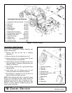
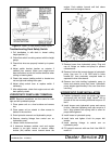
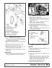
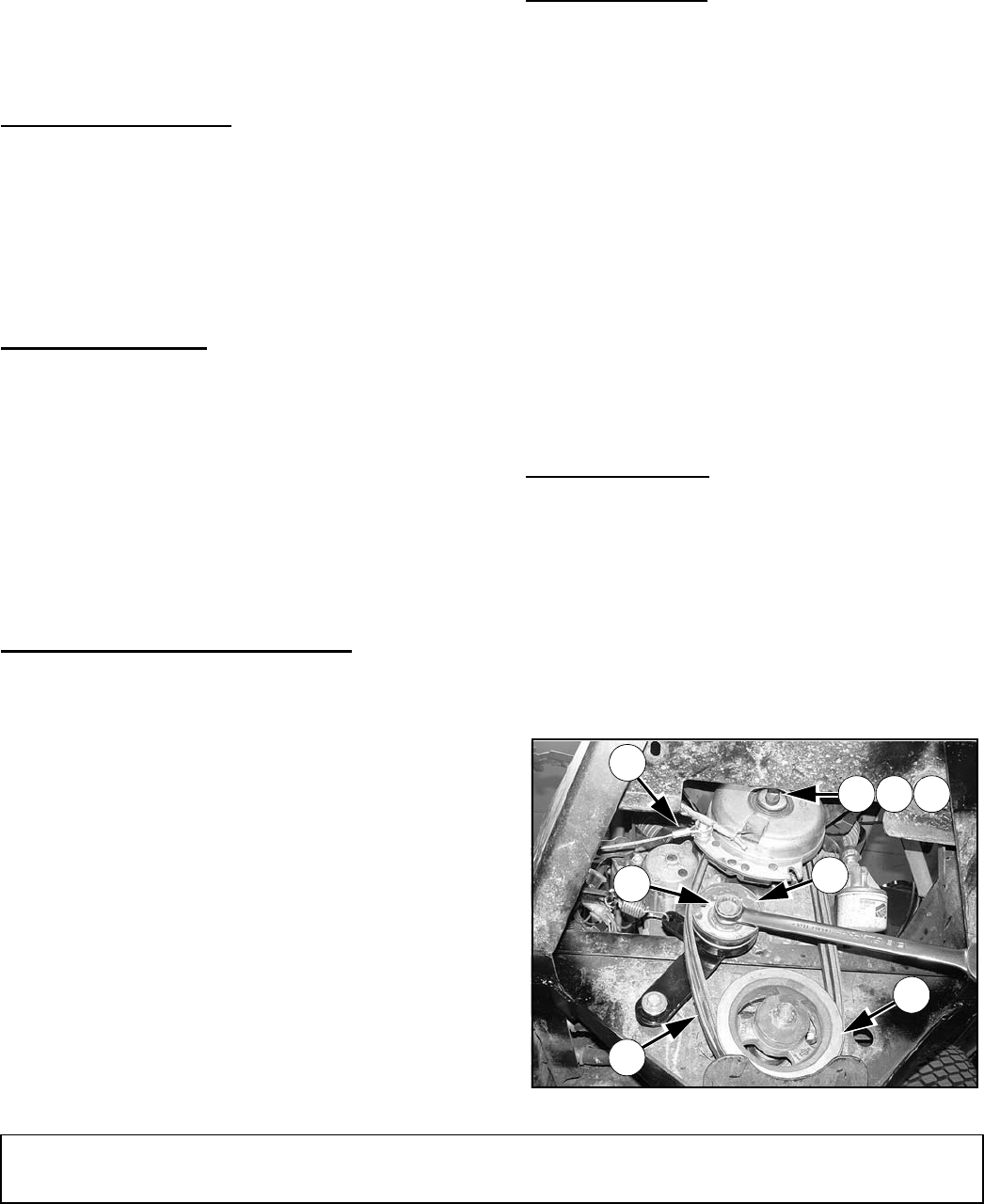
Remove Components (Figure 14 & Figure 15)
1. Position Mow’n Machine on a level work area.
2. Set parking brake, stop engine, and remove key.
NOTE: Photo in Figure 14 was taken from underneath
the power unit for clarification. All work can be per-
formed from above.
NOTE: It may be easier to rework clutch if you first
remove counterweights from the rear of the power unit.
Figure 14. Clutch and Sheave Assembly
47
22
16
21 8 20
2
6
DP9


