


12 Operation
MAN0646 (7/6/2007)
CONTROLS AND SWITCHES
Know your controls and how to stop engine and
attachment quickly in an emergency.
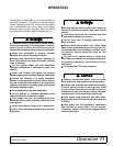
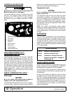
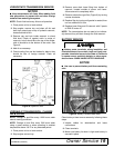
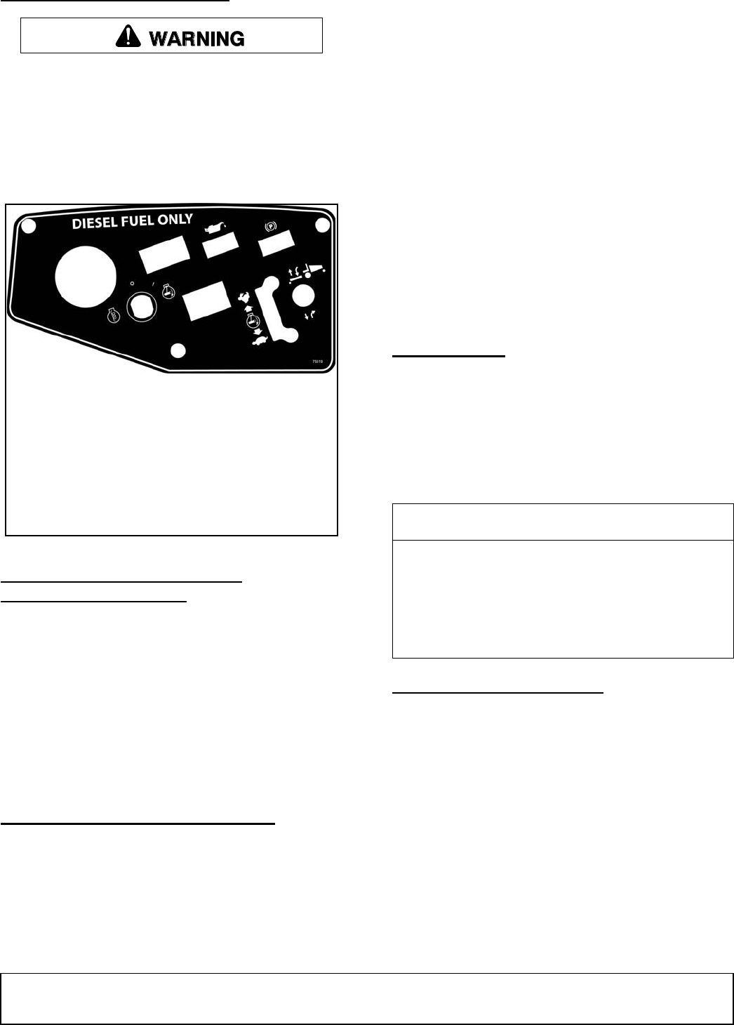
Control and indicator console is located on the right
fuel tank. This console contains controls needed to
operate this unit. PTO switch (2) is used to engage
attachments: pull up to engage, push down to disen-
gage.
Figure 1. Console Control Locations
DECK HEIGHT/POWER TILT™
ADJUSTMENT SWITCH
The deck height and Power Tilt™ switch is used with
MXT or MX deck equipped with the Power Tilt™ Kit.
Push the toggle switch forward to raise the deck and
pull back to lower the deck to the desired cutting
height. For Power Tilt™ operation, pull back and hold
the toggle switch to lower the deck and cycle through to
the tilt position. Release switch when deck reaches
maximum tilt position. To lower the deck, push and hold
toggle switch until it cycles to the desired cutting
height. NOTE: Power Tilt™ feature must not be used
when sitting in the seat.
BRAKE & TEMPERATURE LIGHTS
Brake Light
NOTICE
■ Do not operate with parking brake engaged or
damage to the brake adjustment will occur.
The brake light indicates when the brake is engaged.
To ensure light is operating properly, engage parking
brake and turn ignition key switch to the “ON” position.
Control panel brake light (3) should be on.
Temperature Light
NOTICE
■ For overheating, clean radiator grill and check
engine coolant level.
The temperature light will alert you when the engine
temperature is excessive. The temperature light sys-
tem is not intended to shut the engine off or prevent
operation; it is designed to provide notification. If tem-
perature light starts to flash during operation, discon-
tinue operation. The light is programed to flash at 220°
fahrenheit and above.
NOTE: The radiator and prescreen require regular
cleaning to prevent engine overheating. Clean the pre-
screen daily and the radiator fins every 40 hours. Do
not use high pressure on radiator fins to avoid radiator
damage.
HOUR METER
The hour meter is programed to alert the operator at
various service intervals. The change oil light will flash
at 20 hours (initial break in) and every 100 hours after.
The light will flash for a period of 4 hours (alternating
between hours & change oil) and than resume normal
mode. The hour glass will flash every second indicating
it’s in running mode.
SAFETY SWITCH SYSTEM
Several safety switches are incorporated in the unit’s
design to prevent it from being started out of NEUTRAL
(handles pivoted outward) or with PTO engaged.
The PTO control must be in the “OFF” position and the
steering handles in the NEUTRAL position before unit
can be started.
A safety switch behind the operator’s seat will cause
the engine to stop if the operator leaves the seat with
the PTO or steering handles engaged. The engine will
also stop if the steering handles are moved from NEU-
TRAL while the parking brake is engaged. It will not run
if the deck jumper wire (for Power Tilt™ operation) is
not connected to the wire harness or the deck safety
switch is disengaged.
1. Temperature gauge
2. PTO switch
3. Brake light
4. Oil light
5. Ignition switch
6. Hour meter
7. Throttle control
8. Deck height switch
1
2
3
4
5
6
7
8
Service Intervals
20 hrs Engine oil change (break in)
100 hrs Engine oil change & filter
500 hrs Hydraulic oil change & filter (see
hydraulic transmission - change oil
& filter, page 19)
(Rev. 1/7/2010)