


Incorrectcable adjustment could cause
the wheels andtines to rotate unexpect-
edly. Follow adjustment procedures
carefully. Failure to do so could result
in personalinjuryorpropertydamage.
4. Checkfor correct spring/cable tension
as instructed in Section5, Checkingand
Adjusting ForwardClutch Belt Tension.
5. When tension is correct, tighten the
two jam nuts (B) securely.
STEP5: CHECKTRANSMISSION
GEAROIL LEVEL
Thetransmission was filled with gear oil
at the factory. However,be sureto check
the oil levelat this time to makecertain it
iscorrect.
IMPORTANT:Do not operatethe tiller if
the gear oil level is low. Doingso will
result in severedamageto the transmis-
sion components.
1. With the tiller on levelground, pull the
Depth Regulator Lever (R, Figure2-13)
backand then slide it to the second notch
from the top. NOTE:If the leverdoes not
move,lift the tine hoodflap and look for a
plastictie securing the leverin place. Cut
and removethe tie.
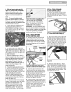
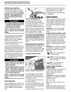
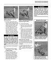
2. Removethe oil levelcheck plug (M,
Figure2-10) on the left-side of the trans-
mission. (Dueto dried painton the plug
threads, it may require someforce to
removethe plug the first time.) The gear
oil levelis correct if oil starts to flow out
ofthe hole asthe plug is removed. If so,
securely reinstall the plug.
Figure2-10: Gearoil level checkplug.
3. If oil does notflow from the check
hole,add oil asfollows:
NOTE:Donot useautomatic transmission
fluid or motor oil in the transmission.
(a) Cleanareaaround the fill hole (N,
Figure2-11) and unscrewgear oil fill
plug.
Figure2-11: Addinggearoil.
(b) If adding only a few ouncesof gear
oil, useAPI ratedGL-4 or GL-5 gear oil
havinga viscosity of SAE140, SAE85W-
140 or SAE80W-90. If refilling an empty
transmission, useonly GL-4 gearoil
havinga viscosity of SAE85W-140 or
SAE140.
(c) Usinga cleanfunnel, slowly addgear
oil until it flows from the gear oil level
check hole (N, Figure2-11).
(d) Reinstalland tighten securelythe gear
oil fill plug (M, Figure2-10).
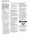
STEP 6: ATTACHWHEEL GEAR
LEVER
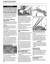
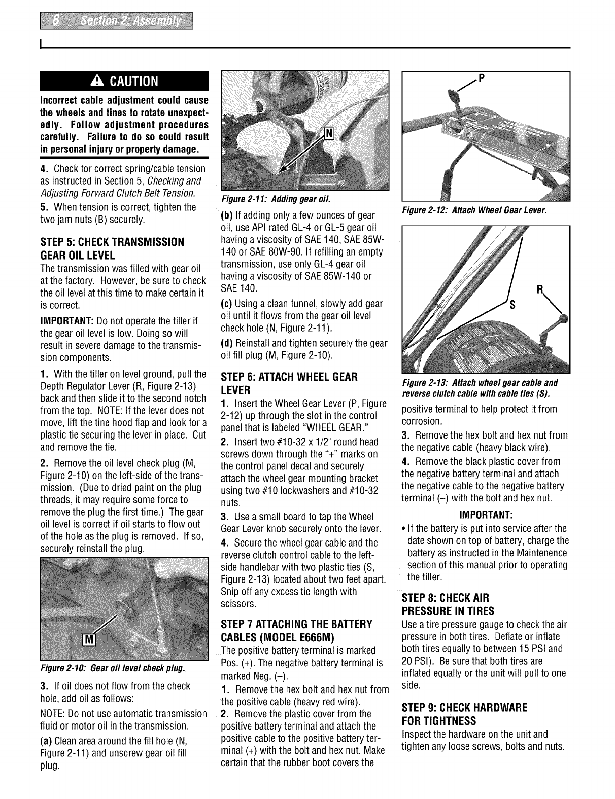
1. Insert the WheelGearLever(P, Figure
2-12) up through the slot in the control
panelthat is labeled"WHEELGEAR."
2. Insert two #10-32 x 1/2" round head
screws down through the "+" marks on
the control paneldecaland securely
attach thewheel gear mounting bracket
usingtwo #10 Iockwashersand #10-32
nuts.
3. Usea small board to tap the Wheel
GearLeverknobsecurely onto the lever.
4. Securethe wheelgear cableand the
reverseclutch control cableto the left-
side handlebarwith two plasticties (S,
Figure2-13) locatedabout two feet apart.
Snip off anyexcesstie length with
scissors.
STEP7 ATTACHINGTHE BATTERY
CABLES(MODEL E666M)
The positive batteryterminal is marked
Pos. (+). Thenegative batteryterminal is
marked Neg.(-).
1. Removethe hex bolt and hex nut from
the positive cable(heavy red wire).
2. Removethe plasticcover from the
positive batteryterminal and attachthe
positive cableto the positive batteryter-
minal (+) with the bolt and hex nut. Make
certain that the rubber boot coversthe
Figure2-12: AttachWheel GearLever.
Figure2-13: Attachwheel gear cableand
reverseclutchcable with cableties(S).
positive terminal to help protect itfrom
corrosion.
3. Removethe hexbolt and hexnut from
the negativecable(heavy blackwire).
4. Removethe black plastic cover from
the negativebatteryterminal and attach
the negativecableto the negativebattery
terminal (-) with the bolt and hex nut.
IMPORTANT:
• If the battery is put into serviceafter the
dateshown on top of battery, chargethe
batteryas instructed in the Maintenence
sectionof this manual prior to operating
the tiller.
STEP 8: CHECKAIR
PRESSURE IN TIRES
Usea tire pressuregaugeto check the air
pressure in bothtires. Deflateor inflate
both tires equallyto between15 PSI and
20 PSI). Besure that both tires are
inflated equally or the unit will pull to one
side.
STEP 9: CHECK HARDWARE
FOR TIGHTNESS
Inspect the hardwareon the unit and
tighten anyloose screws, bolts and nuts.