


4. With theforwardclutchcable (N,
Figure2-4) onthe inside of handlebar,
position the handlebarendson the
outside of thetwo mounting tabs (IVI,
Figure2-3) on the transmission top
cover.
NOTE:Thecurved handlebarheight
adjustment bracketappears asshown in
C,Figure2-3 for non-electricstart units.
Forelectric start units, the bracket is loos-
ened and moved to one side.
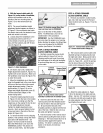
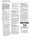
5. Loosely attachthe handlebarsto the
mounting tabs with two 3/8-16 x 1"
screws (headsof screws go to inside of
tabs), 3/8" flat washers and 3/8"-16 lock
nuts (0, Figure2-4).
Figure 2-4: Attachhandlebars.
6. Onelectric start units, reattach the
heightadjustment bracket(A, Figure2-2).
Tighten both screws securely. Makesure
the handlebarcross-brace (B, Figure2-3)
is under the bracket.
7. Move the handlebars up or down to
align the threaded hole in the cross-brace
with one of the four slots in the curved
heightadjustment bracket. Placethe
keyedwasher (E,Figure2-3) on the
flange head heightadjustment screw (F)
with the raised keys(edges) ofthe
washer facing down.
8. Threadthe heightadjustment screw
(F, Figure2-3) intothe hole inthe handle-
bar cross-brace, making sure that the
raisedkeyson the washer fit into the slot
on the height adjustment bracket.
Tighten the height adjustment screw
securely. Next,securelytighten the two
screws and nuts in the endsof the han-
dlebar (M, Figure2-3).
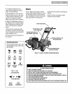
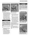
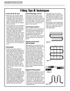
9. To removethe tiller from its shipping
platform, first carefully unwrapthe wheel
gear cable (with attachedlever- see
Figure2-5) from around the chassis.
Movethe WheelGearLever (G)to the
DISENGAGEposition--this allows the
wheels to rotatefreely. Usethe handle-
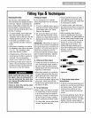
STEP 4: ATTACHFORWARD
CLUTCH CONTROL CABLE
1. Removeanyfasteners (rubber bands,
tape, etc.) that may securethe Forward
Clutch Control levers (J, Figure2-7) to the
handlebar.
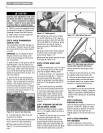
Figure2-5: CarefullyunwrapWheelGear
LeverandmovelevertoDISENGAGE.
barsto roll thetiller off the platform.
NOTE:TheWheel GearLever will be
installed later in this procedure.
IMPORTANT: Usethe DISENGAGEposi-
tion only whenthe engine is not running.
Beforestarting the engine,the Wheel Gear
Levermust be placed inthe ENGAGE
position (seeSection 3for details).
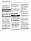
STEP3: ATTACH REVERSE
CLUTCH CONTROL CABLE
1. Carefullyunwrap the reverseclutch
control cable(H, Figure2-6) from its
shipping position and route it up along
the insideedge ofthe left side handlebar.
A knoband large hexnut (I) is installed
on the cable.
I
LeftSide ReverseClutch]
Handlebar ControlKnob
I
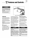
Figure2-7: ForwardClutchControllevers
(J). Forwardclutchcontrollinkage(K).
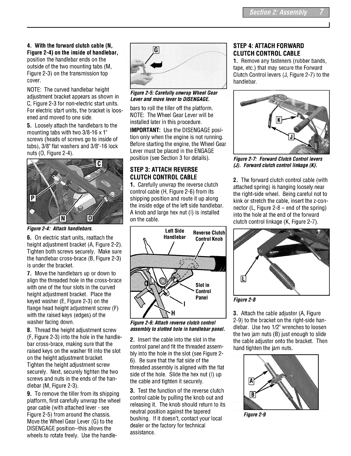
2. Theforward clutch control cable(with
attachedspring) is hanging loosely near
the right-side wheel. Being careful not to
kink or stretch the cable,insert thez-con-
nector (L, Figure2-8 - end of the spring)
into the hole at the end of the forward
clutch control linkage(K, Figure 2-7).
Figure2-6: Attachreverse clutchcontrol
assemblytoslottedhole in handlebarpanel.
2. Insertthe cableinto the slot in the
control paneland fit the threadedassem-
bly into the hole in theslot (seeFigure2-
6). Besurethat theflat side of the
threadedassembly is aligned with the flat
side of the hole. Slide the hex nut (I) up
the cableand tighten it securely.
3. Test thefunction of the reverseclutch
control cableby pulling the knob out and
releasingit. Theknob should return to its
neutral position against the tapered
bushing. If it doesn't, contact your local
dealeror the factory for technical
assistance.
Figure2-8
3. Attachthe cable adjuster (A, Figure
2-9) to the bracket on the right-side han-
dlebar. Usetwo 1/2"wrenchesto loosen
the two jam nuts (B) just enoughto slide
the cableadjuster onto the bracket. Then
hand tighten the jam nuts.
Figure2-9