


2 Assembly
To prevent personal injury or property
damage,do notstartthe engine until all
assembly steps are complete and you
havereadand understandthe safetyand
operatinginstructionsin this Manual.
INTRODUCTION
Carefullyfollow these assembly steps to
correctly prepareyour tiller for use. It is
recommendedthat you readthis Section
in its entirety before beginningassembly.
INSPECTUNIT
Inspectthe unit andcarton for damage
immediatelyafter delivery. Contactthe
carrier (trucking company) if you find or
suspect damage. Inform them ofthe
damageand request instructions for filing
a claim. To protect your rights, put your
claim in writing and mail a copy to the
carrier within 15 days afterthe unit has
beendelivered.Contact usat the factory if
you needassistancein this matter.
UNPACKINGANDASSEMBLY
INSTRUCTIONS
STEP 1: UNPACKING INSTRUCTIONS
1. Removeanycardboard inserts and
packagingmaterialfrom the carton.
Removeanystaples from the bottom of
the carton and removethe carton.
2. Cutthe large,plastic tie strap that
securesthe transmission tubeto the ship-
ping pallet. Leavethe handlebarson top
of the tiller to avoid damaginganycables.
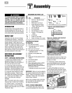
3. A bag with loose hardwareis inside
the literature envelope. Checkthe con-
tents against thefollowing list and Figure
2-1. Contactyour local dealeror the
factory if any items are missing or
damaged.
NOTE:For electric start units, a second
hardwarebag is located nearthe battery.
4. Thetiller is heavy. You should not
attempt to remove it from the shipping
platform until instructed to do so in these
"Assembly" steps.
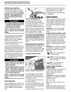
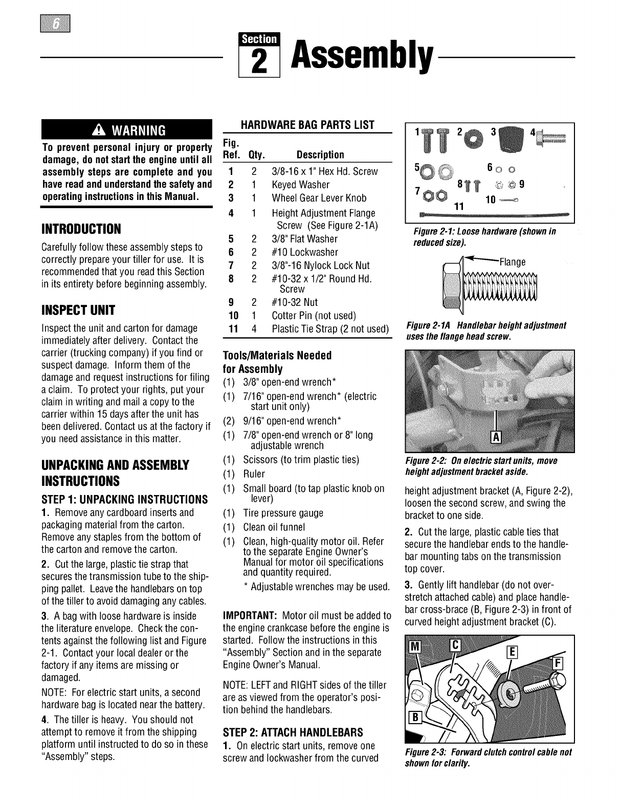
HARDWARE BAG PARTS LIST
Fig.
Ref. Qty. Description
1 2 3/8-16 x 1" HexHd. Screw
2 1 KeyedWasher
3 1 WheelGearLeverKnob
4 1 Height Adjustment Flange
Screw (SeeFigure2-1A)
5 2 3/8" FlatWasher
6 2 #10 Lockwasher
7 2 3/8"-16 Nylock Lock Nut
8 2 #10-32 x 1/2" RoundHd.
Screw
9 2 #10-32 Nut
10 1 Cotter Pin (not used)
11 4 PlasticTie Strap (2 not used)
Tools/Materials Needed
for Assembly
(1) 3/8" open-endwrench*
(1) 7/16" open-endwrench* (electric
start unit only)
(2) 9/16" open-endwrench*
(1) 7/8" open-endwrench or 8" long
adjustable wrench
(1) Scissors (to trim plasticties)
(1) Ruler
(1) Small board (to tap plastic knob on
lever)
(1) Tire pressuregauge
(1) Cleanoilfunnel
(1) Clean,high-quality motor oil. Refer
to the separateEngineOwner's
Manualfor motor oil specifications
and quantity required.
* Adjustablewrenches may be used.
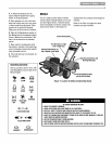
IMPORTANT:Motor oil must beaddedto
the enginecrankcasebeforethe engine is
started. Followthe instructions in this
"Assembly" Sectionand in the separate
EngineOwner's Manual.
NOTE:LEFTand RIGHTsides of thetiller
are asviewedfrom the operator's posi-
tion behindthe handlebars.
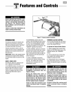
STEP 2: ATTACHHANDLEBARS
1. On electric start units, removeone
screw and Iockwasherfrom thecurved
5@_, 60 o
8_ @©9
7_ 10_
11
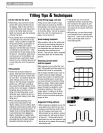
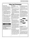
Figure2-1:Loosehardware(shownin
reducedsize).
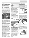
Figure2-1A Handlebarheightadjustment
usestheflangeheadscrew.
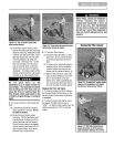
Figure2-2: Onelectric startunits, move
heightadjustmentbracket aside.
heightadjustment bracket (A, Figure2-2),
loosenthe secondscrew, and swing the
bracketto one side.
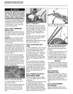
2. Cutthe large,plastic cableties that
securethe handlebarends to the handle-
bar mounting tabs on the transmission
top cover.
3. Gently lift handlebar (do not over-
stretch attachedcable) and place handle-
bar cross-brace (B, Figure 2-3) in front of
curved heightadjustment bracket (C).
Figure2-3: Forwardclutchcontrolcablenot
shownforclarity.