


Before inspecting, cleaning or servicing the machine, shutoff engine, wait for all moving parts to
come to a complete stop, disconnect spark plug wire and move wire away from spark plug.
Remove the keyfrom the keyswitch on unitsso equipped.
Failure to follow these instructionscan result in serious personal injury or property damage.
WHEELGEARCABLEADJUSTMENT OFFSEASONSTORAGE
When the WheelGearLeveris in DISEN-
GAGE,the wheels will roll freely (free-
wheel). Thewheels should not roll freely
whenthe lever is in ENGAGE.If the
wheels roll freely whenthe Wheel Gear
Leveris in ENGAGE,the wheel gearcable
needsto be adjustedas described below.
1. With the engineshut off and the spark
plug wire disconnected, put the Wheel
GearLeverin ENGAGE.
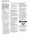
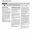
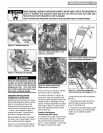
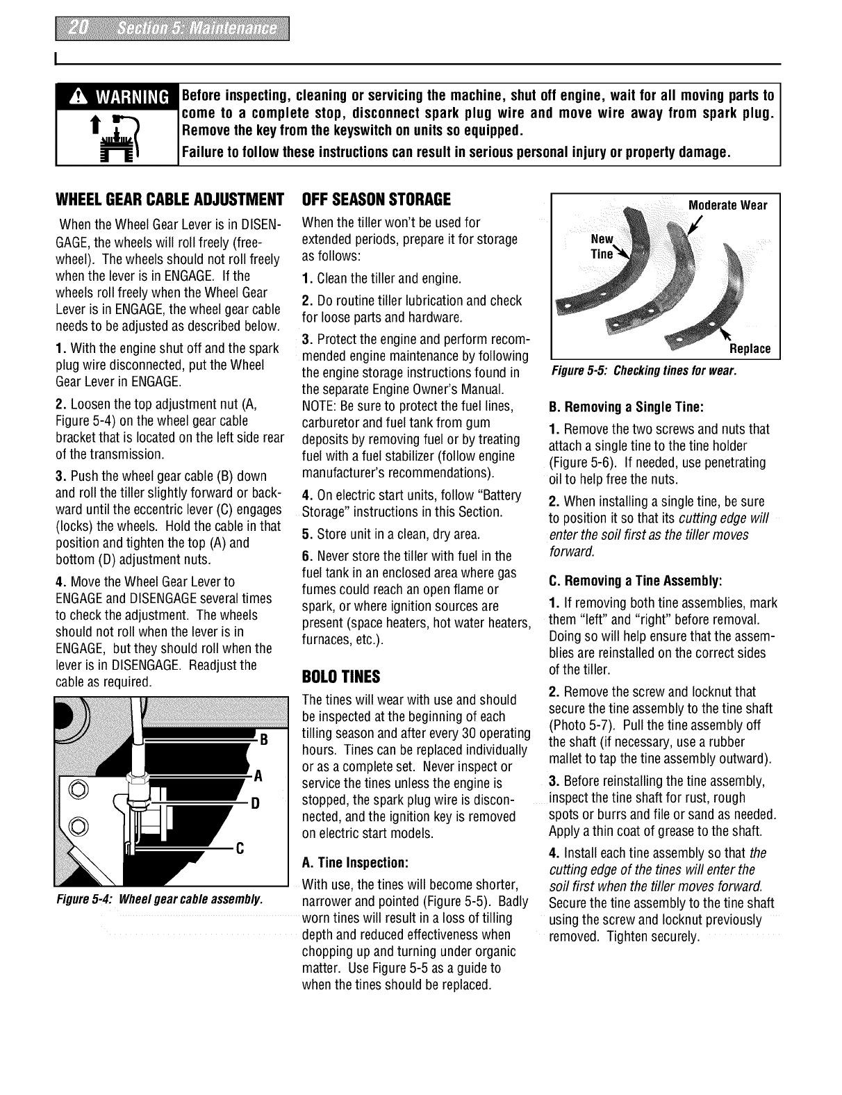
2. Loosenthe top adjustment nut (A,
Figure5-4) on the wheelgear cable
bracketthat is located on the left side rear
of thetransmission.
3. Pushthe wheel gearcable (B) down
and roll thetiller slightly forward or back-
ward until the eccentric lever (C)engages
(locks) the wheels. Holdthe cable in that
position andtighten the top (A) and
bottom (D) adjustment nuts.
4. Movethe WheelGear Leverto
ENGAGEand DISENGAGEseveraltimes
to checkthe adjustment. Thewheels
should not roll when the leveris in
ENGAGE,but they should roll whenthe
leveris in DISENGAGE.Readjustthe
cableasrequired.
C
Figure5-4: Wheelgear cableassembly.
Whenthe tiller won't beusedfor
extended periods, prepare it for storage
asfollows:
1. Cleanthe tiller and engine.
2. Do routine tiller lubrication and check
for loose parts and hardware.
3. Protect the engineand perform recom-
mendedengine maintenancebyfollowing
the engine storage instructions found in
the separateEngineOwner's Manual.
NOTE:Besureto protectthe fuel lines,
carburetor andfuel tank from gum
deposits by removing fuel or by treating
fuel with a fuel stabilizer (follow engine
manufacturer's recommendations).
4. On electric start units, follow "Battery
Storage" instructions in this Section.
5. Store unit in a clean,dry area.
6. Neverstore thetiller with fuel in the
fuel tank in an enclosedarea wheregas
fumes could reachan openflame or
spark, or where ignition sources are
present (spaceheaters,hot water heaters,
furnaces, etc.).
BOLOTINES
Thetines will wear with useand should
be inspectedat the beginning of each
tilling season andafter every30 operating
hours. Tines can be replaced individually
or as acomplete set. Neverinspector
servicethe tines unlessthe engine is
stopped, the spark plug wire is discon-
nected,and the ignition key is removed
on electric start models.
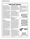
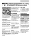
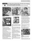
A. Tine Inspection:
With use,thetines will becomeshorter,
narrowerand pointed (Figure5-5). Badly
worn tines will result in a loss of tilling
depth and reducedeffectiveness when
chopping up and turning under organic
matter. UseFigure5-5 asa guideto
when thetines should be replaced.
ModerateWear
Replace
Figure5-5: Checkingtinesforwear.
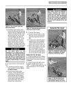
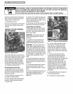
B. Removinga SingleTine:
1. Removethe two screws and nuts that
attacha single tine to the tine holder
(Figure5-6). If needed,use penetrating
oil to helpfree the nuts.
2. When installing a single tine, besure
to position it so that its cutting edge will
enterthe soil first as the tiller moves
forward.
C. Removinga TineAssembly:
1. If removing both tine assemblies, mark
them "left" and "right" beforeremoval.
Doingso will help ensurethat the assem-
bliesare reinstalled onthe correct sides
of the tiller.
2. Removethe screw and Iocknut that
securethe tine assembly to the tine shaft
(Photo5-7). Pull the tine assembly off
the shaft (if necessary,usea rubber
malletto tap the tine assembly outward).
3. Beforereinstalling the tine assembly,
inspectthetine shaft for rust, rough
spots or burrs andfile or sand as needed.
Apply athin coat of greaseto the shaft.
4. Installeach tine assembly sothat the
cutting edge of the tines will enter the
soil first when the tiller moves forward.
Securethe tine assembly to the tine shaft
usingthe screw and Iocknut previously
removed. Tighten securely.