


5 Maintenance
Before inspecting, cleaning or
servicing the machine, shut off engine,
wait for all moving parts to come to a
complete stop, disconnect spark plug
wire and move wire away from spark
plug. Remove ignition key on electric
start models.
Failure to follow these instructionscan
resultin seriouspersonalinjury or prop-
ertydamage.
MAINTENANCESCHEDULE
PROCEDURE NOTES
Checkmotor oil level 2, 3
Cleanengine 2, 7
Checkdrive belttension 1, 4
Checknuts and bolts 1, 4
Changemotor oil 1, 4, 6
Lubricate tiller 4
Service foam pre-cleaner airfilter 7
(if soequipped)
Service paper air filter (if soequipped) 7
Checkgear oil levelin transmission 1, 5
Checktines for wear 5
Checkair pressure intires 5
Service spark plug 7
NOTES
1- After first 2 hours of break-in operation.
2 - Beforeeach use.
3 - Every5 operating hours.
4 - Every 10operating hours.
5 - Every30 operating hours.
6 - More frequently in dusty ordirty conditions.
7 - SeeEngine Owner'sManual for service
recommendations.
6 - Whichevertime interval occurs first.
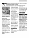
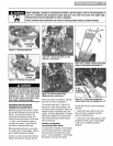
TILLERLUBRICATION
D
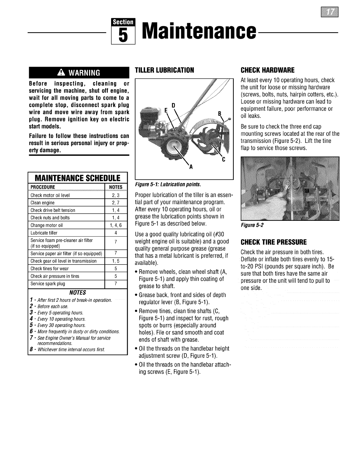
Figure5-1: Lubricationpoints.
Proper lubrication of thetiller isan essen-
tial part ofyour maintenanceprogram.
After every 10 operating hours, oil or
greasethe lubrication points shown in
Figure5-1 as described below.
Usea good quality lubricating oil (#30
weight engine oil is suitable) anda good
quality general purpose grease (grease
that hasa metallubricant is preferred, if
available).
• Removewheels,cleanwheel shaft (A,
Figure5-1) andapply thin coating of
greaseto shaft.
• Greaseback,front and sides of depth
regulator lever(B, Figure5-1).
• Removetines, cleantine shafts (C,
Figure5-1) and inspectfor rust, rough
spots or burrs (especiallyaround
holes). Fileor sand smooth and coat
endsof shaft with grease.
• Oilthe threads onthe handlebarheight
adjustment screw (D, Figure5-1).
• Oilthe threads onthe handlebarattach-
ing screws (E,Figure5-1).
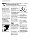
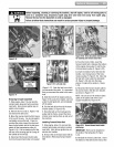
CHECKHARDWARE
At least every 10 operating hours, check
the unit for loose or missing hardware
(screws, bolts, nuts, hairpin cotters, etc.).
Looseor missing hardwarecan leadto
equipment failure, poor performanceor
oil leaks.
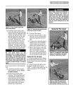
Besureto checkthe three end cap
mounting screws locatedat the rear of the
transmission (Figure5-2). Lift the tine
flap to servicethose screws.
Figure5-2
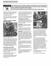
CHECKTIRE PRESSURE
Checkthe air pressure in bothtires.
Deflateor inflate bothtires evenlyto 15-
to-20 PSI (pounds per square inch). Be
sure that bothtires havethe sameair
pressureor the unit will tendto pull to
one side.