


8
Section 2: Assembly
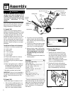
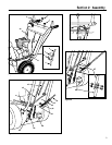
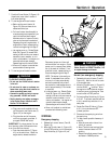
6. Remove the washer and locknut from
the screw (M, Figure 2-4) in the worm
gear assembly (L). Position the worm
gear assembly on the mounting
bracket as follows:
a. Engage the worm gear threads 1/2-
way with the teeth on the flange of
the discharge chute base (rotate
chute as needed).
b. The length of the worm gear should
be centered with the teeth on the
flange of the discharge chute base.
c. Reinstall the washer and locknut on
the screw (M) and tighten securely.
7. Insert the flexible fins on the plastic
snow deflector (N, Figure 2-4) inside
the chute deflector cap (O). Close the
deflector cap by pulling the lever (P)
outward and moving the deflector cap
down. Release the lever to secure the
deflector cap in one of the discharge
angle selector holes.
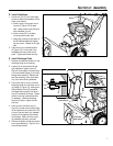
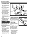
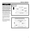
F. Attach Chute Control Rod
1. Remove the plastic tie that secures the
auger drive control rod (AA, Figure 2-
5) to the right handlebar. Next, re-
move the plastic tie that secures the
chute crank rod (short rod with plastic
swivel blocks) to the auger drive con-
trol rod.
2. Pull the chute crank rod (Z, Figure 2-5)
up through the top of the control
panel.
3. Attach the chute control rod sections
(S and U, Figure 2-5) as follows:
a. Insert the angled end of the chute
control rod, (U, Figure 2-5 inset)
into the hole in the swivel block (V)
that is attached to the end of the
chute crank rod (S).
b. Insert a cotter pin (W) through the
hole in the chute control rod (U) and
spread the ends of the cotter pin.
4. Position the chute control rod support
bracket (Y, Figure 2-6) against the un-
derside of the handlebar console as
shown. Secure the bracket with the
two #10–24 x 3/8" Phillips pan head
screws and #10–24 locknuts supplied.
5. Rotate the chute control crank (Z,
Figure 2-5). The discharge chute
should turn freely, but with enough re-
sistance to prevent free rotation of the
discharge chute during snow removal
operation. Adjust the worm gear as-
sembly bracket (L, Figure 2-4) as nec-
essary to prevent binding.
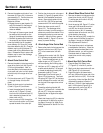
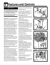
G. Attach Auger Drive Control Rod
1. Remove the plastic tie that secures the
auger drive control arm (AD, Figure
2-7) to the transmission shift arm
(AB).
2. The auger drive control rod (AA, Figure
2-7) has been pre-adjusted at the fac-
tory. To avoid misadjustment, do not
rotate the jam nut (AT, Figure 2-7)
while completing the following steps.
3. Hold jam nut (AT) in place with a 7/16"
wrench and use another 7/16" wrench
to thread the adjusting thimble (AS)
downward a total of 12 turns.
4. Raise Auger Drive Control Lever (X,
Figure 2-5) all the way up. Then hook
the spring (AC, Figure 2-7) at the lower
end of the auger drive control rod (AA)
into the hole in the auger drive control
arm (AD).
5. Thread the adjusting thimble (AS,
Figure 2-7) upward until it contacts the
jam nut (AT). Using two wrenches,
tighten the jam nut against the adjust-
ing thimble.
6. Check that the spring (AC) is under the
correct amount of tension by perform-
ing Steps 2 through 5 of Auger Drive
Belt(s) Adjustment in Section 5 of this
manual.
H. Attach Wheel Drive Control Rod
1. Remove the plastic tie that secures the
wheel drive control rod (AE, Figure 2-
7) and the gear shift control rod (AF)
to the left handlebar.
2. Hook the spring (AG, Figure 2-7) at the
lower end of the wheel drive control
rod (AE) into the hole in the wheel
drive control arm (AH). If necessary,
raise the wheel drive control arm (AH)
while attaching the spring.
3. Check that the spring (AG) is under the
correct amount of tension by perform-
ing Steps 1 through 4 of Wheel Drive
Disc Adjustment in Section 5.
4. The wheel drive control rod has been
pre-adjusted at the factory. When the
engine is started, as described in the
Operation section, you will be given a
functional check to make sure the
wheel drive control rod is properly
adjusted.
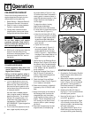
I. Attach Gear Shift Control Rod
1. Place the Gear Shift Select Lever
(T, Figure 2-5) in the No. 5 position.
2. Gently push the transmission shift arm
(AB, Figure 2-8) fully downward.
3. Align the holes in the transmission
shift arm (AB) and the lower end of the
gear shift control rod (AF). If the holes
do not align, follow the Gear Shift Rod
Adjustment procedure in Section 5.
4. Use two 1/4-20 x 3/4 hex head screws
and 1/4-20 locknuts (Figure 2-8) to
attach gear shift control rod (AF) to
transmission shift arm (AB).