


19
The spring length should now measure
9/16" – 11/16" (14–17mm) longer than the
measurement taken in Step 4. If it does
not, loosen the jam nut (AM, Figure 5-8)
and turn the adjuster (AN) to increase or
decrease the length of the spring. Hold
the adjuster and tighten the jam nut (AM)
when the correct spring length is ob-
tained. Re-check the measurements and
adjust if needed.
NOTE: 1-1/4 turns of the adjuster equals
1/16" (1.5mm) of spring extension.
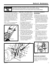
GEAR SHIFT ROD ADJUSTMENT
1. With the engine stopped and the spark
plug wire disconnected, move the gear
shift lever (AU, Figure 5-7) to position
No. 5. Remove the hairpin cotter and
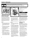
the flat washer from the pivot block (N,
Figure 5-10). Disconnect the pivot
block (N) from the gear shift lever plate
(AV, Figure 5-10).
2. Pull the gear shift control rod (AA,
Figure 5-8) down completely.
3. While holding the gear shift control rod
(AA, Figure 5-8) down, loosen the jam
nut (ZZ, Figure 5-10) and thread the
pivot block (N) up or down as needed
so it fits into the hole in the gear shift
lever plate (AV, Figure 5-10).
4. Reinstall the pivot block (N, Figure 5-
10) into the gear shift control lever hole
and secure with the washer and hairpin
cotter. Secure the jam nut (ZZ, Figure
5-10) against the pivot block (N).
5. Move the gear shift control lever (AU,
Figure 5-7) through the full range of
travel. Check for binding. Refer to the
Drive Disc Clearance Adjustment
instructions, if needed.
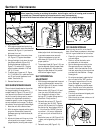
DRIVE DISC CLEARANCE
ADJUSTMENT
If the gear shift rod lever does not move
freely through all the gear positions, ad-
just clearance (AY, Figure 5-9) as follows:
1. With the engine stopped and the spark
plug wire disconnected, loosen jam nut
(AW, Figure 5-8). Rotate adjusting
screw (AX) until rubber drive wheel (T,
Figure 5-9) contacts metal drive disc
(U).
2. Turn the rubber drive wheel (T, Figure
5-9) and the metal drive disc (U) to
find the point of minimum clearance
(AY). (This is where both the drive
wheel [T] and metal disc [U] are
touching.)
3. Adjust the discs at the point of mini-
mum clearance. Loosen adjusting
screw (AX, Figure 5-8) 1/2 turn.
Secure the adjusting screw (AX) in
place, while tightening the jam nut
(AW).
4. Check the clearance (AY, Figure 5-9)
by moving gear shift lever (AU, Figure
5-7) through all positions. Repeat
Step 3 as necessary.
BRAKE ARM ADJUSTMENT
The brake arm adjustment is set at the
factory to 1/16 - 1/8" for proper belt/brake
clearance. Due to wear, this may need
adjustment.
Section 5: Maintenance
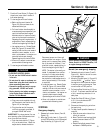
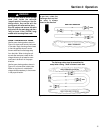
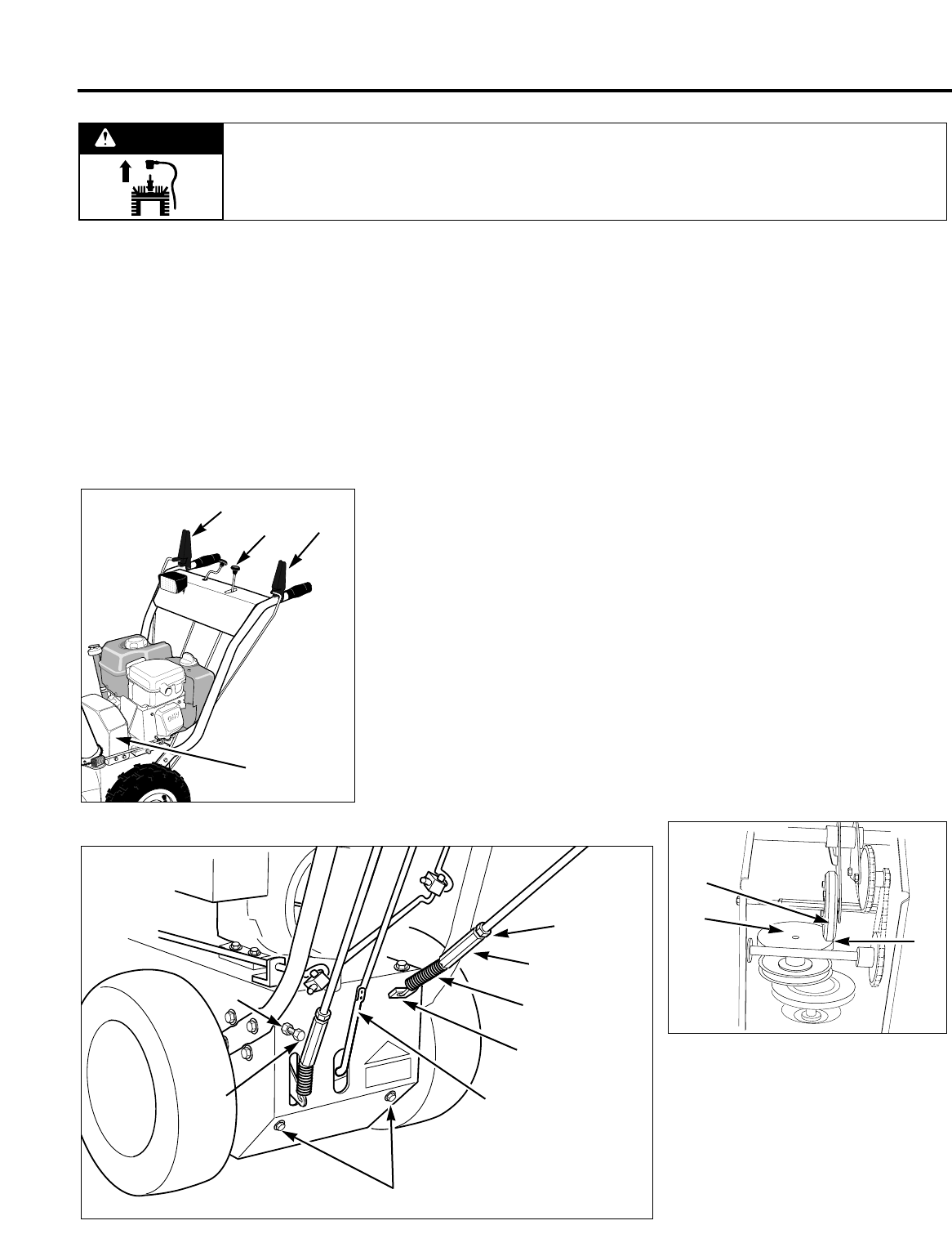
Figure 5-7
AB
AL
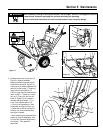
Figure 5-8
Q
AK
AJ
AA
AN
AM
AX
AW
AU
AP
Figure 5-9
AY
T
U
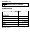
Before inspecting, cleaning or servicing the machine, shut off engine, wait for all moving parts to come to
a complete stop, disconnect spark plug wire and move wire away from spark plug.
Failure to follow these instructions can result in serious personal injury or property damage.
WARNING