


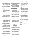
IMPORTANT: Refer to the separate Engine
Owner’s Manual for detailed information
about the controls on the engine.
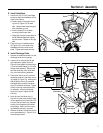
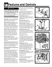
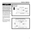
Wheel Drive Control Lever (A, Fig. 3-1)
This lever controls the engagement of the
wheel drive. When the lever is down
against the handlebar and the engine is run-
ning, the wheels will rotate. See Section 5
of this manual for adjustment information.
Auger Drive Control Lever (B, Fig. 3-1)
This lever controls the engagement of the
auger drive. When the lever is down
against the handlebar and the engine is
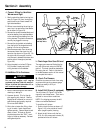
running, the auger (R, Figure 3-4) and
impeller (S) will rotate. See Section 5 of
this manual for adjustment information.
Gear Shift Lever (C, Fig. 3-1)
This lever controls the selection of travel
speeds: five forward and two reverse. See
Section 5 of this manual for adjustment
information.
Discharge Chute Control Rod (D, Fig. 3-1)
This lever controls the direction of the dis-
charge chute. Approximately ten turns of
this crank moves the discharge chute all
the way from one side to the other.
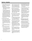
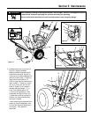
Discharge Chute Deflector Cap and Lever
(E & F, Fig. 3-2)
The discharge chute deflector cap (E) con-
trols the vertical angle of the snow dis-
charge. To adjust the discharge angle,
move the discharge cap by pulling lever (F)
outward and moving the discharge deflec-
tor cap up or down. The discharge chute
deflector cap should usually be adjusted to
a low angle, especially in windy conditions.
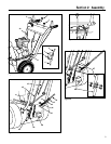
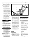
Fuel Shut-Off Valve (G, Fig. 3-3)
The fuel shut-off valve controls fuel flow
from the fuel tank to the carburetor. Turn
valve 1/4 turn clockwise to OFF (closed)
position when storing or transporting unit.
Turn valve 1/4 turn counterclockwise to
ON (open) position before starting engine.
Throttle (H, Fig. 3-3)
The throttle controls the speed of the en-
gine and is used to stop the engine.
NOTE: The engine lubrication and cooling
systems operate best at full throttle.
Primer Button (J, Fig. 3-3)
The primer button pumps small amounts
of gasoline into the engine to improve cold
weather starting.
Recoil Starter (K, Fig. 3-3)
Used for pull-starting the engine.
Stop Switch Key (L, Fig. 3-3)
This key-like device is used to stop the en-
gine (the Throttle, as described above, can
also be used to stop the engine). Push the
key in before starting the engine. Pull it out
to stop the engine. Do not twist the key.
Electric Starter (M, Fig. 3-3)
The electric starter uses 120VAC house
current to start the engine. Use only the
electric cord provided with the unit to con-
nect to house current.
Choke Knob (N, Fig. 3-3)
The choke knob controls the air/gasoline
mixture that is fed into the engine. Use
the CHOKE setting when starting the en-
gine and the RUN setting during operation.
A warm engine may not require choking
when starting.
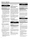
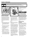
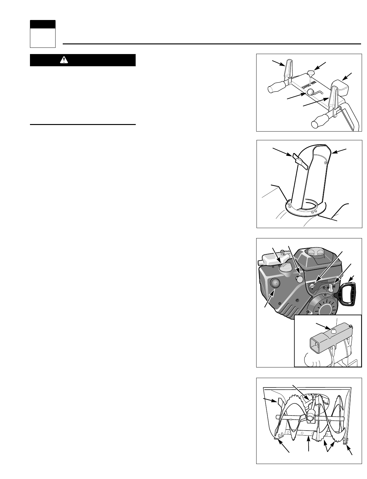
Skid Shoes (O, Fig. 3-4)
The skid shoes control the distance be-
tween the collector (auger/impeller) hous-
ing/scraper blade and the ground. This
distance should be adjusted to clear any
uneven or gravel surfaces. Refer to
Section 5 for adjustment information.
Scraper Blade (P, Fig. 3-4)
The scraper blade (P) clears snow close to
the pavement. Refer to Section 5 for ad-
justment information.
Light (T, Fig. 3-2)
The light is powered by the engine and
stays on during engine operation.
Handlebar Warmers
The handlebar warmers are activated when
the engine is running. The handlebar grips
will warm gradually to the touch.
Figure 3-3
Figure 3-4
P
R
R
S
O
O
K
J
Figure 3-1
Figure 3-2
F
E
D
B
A
C
T
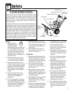
Before operating your machine, carefully
read and understand all safety, controls,
and operating instructions in this man-
ual, the separate Engine Owner’s Manual
and on the decals on the machine.
Failure to follow these instructions can
result in serious personal injury.
WARNING
L
N
G
H
Features and Controls
3
Section
11
M