


Section 5: Maintenance
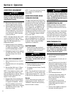
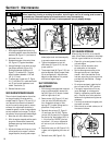
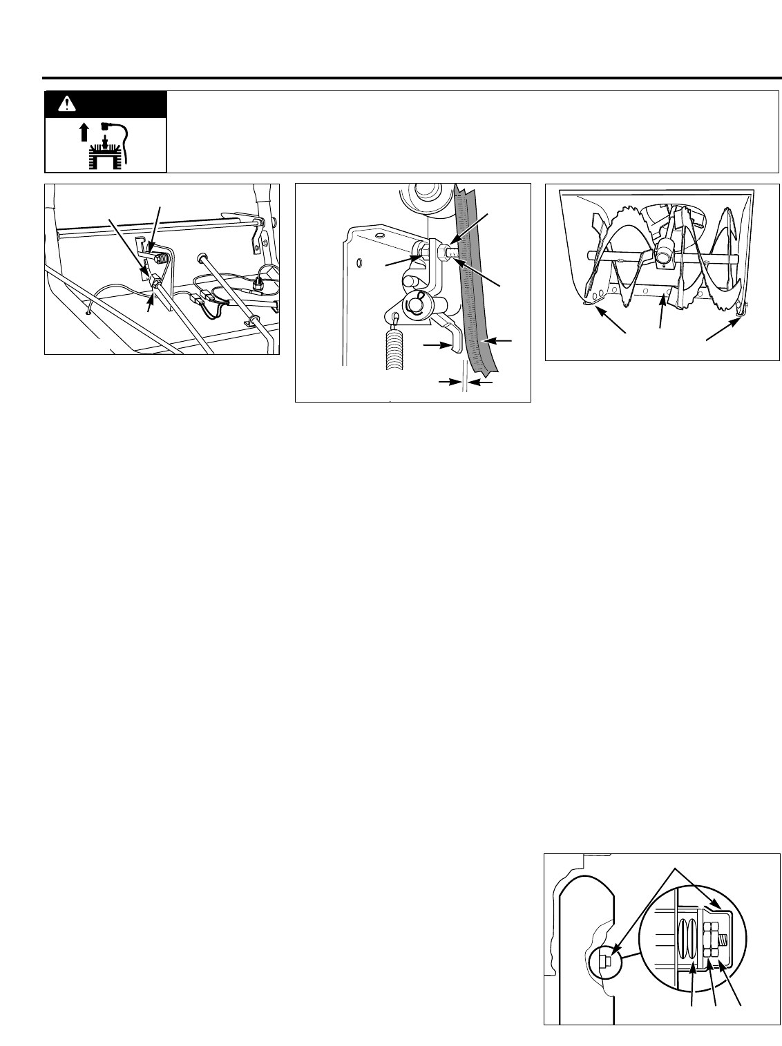
To adjust brake arm:
1. With engine stopped and spark plug
wire disconnected, remove screws and
washers (AB, Figure 5-1) and remove
belt cover from unit.
2. Squeeze the auger drive control lever
(AL, Figure 5-7) against handlebar.
3. Using a flashlight, look down through
the pulleys and belts (Figure 5-6).
Check gap between brake arm (A,
Figure 5-11) and belt (B). The gap
should measure between 1/16" and
1/8" (1.5–3 mm).
4. To adjust gap: Loosen nut (C, Figure
5-11). Hold bolt (D) in place and rotate
nut (E) until proper clearance is ob-
tained. Secure nut (C).
5. Reinstall the belt cover.
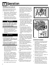
SKID SHOES/SCRAPER BLADE
The unit should be adjusted so the collec-
tor (auger/impeller) housing and the
scraper blade (N, Figure 5-12) are 1/8" (3
mm) above the surface to be cleared. If
the unit is used to clear gravel or uneven
surfaces, this adjustment should be in-
creased so gravel or other foreign objects
are not scooped into the auger. To adjust
the collector housing/scraper blade height:
1. Move the unit onto a level surface.
2. With the engine stopped and the spark
plug wire disconnected, loosen the
hardware securing the skid shoes (M,
Figure 5-12).
3. Adjust skid shoes until they are in the
correct position to support collector
(auger/impeller) housing and scraper
blade (adjust both skid shoes equally
to prevent uneven snow removal).
4. Tighten the hardware to lock the
skid shoes (M, Figure 5-12) into the
proper position.
5. The scraper blade (N, Figure 5-12) can
also be adjusted. Adjust scraper blade
(N) at carriage bolts. Adjust bottom
edge of scraper blade so it is parallel
with bottom edge of auger.
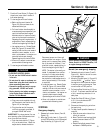
SLIP DIFFERENTIAL
ADJUSTMENT
1. With the engine stopped and the spark
plug wire disconnected, remove hub
cap (AQ, Figure 5-13) at end of wheel
shaft on right side of unit.
2. Remove outer (AR, Figure 5-13) and
inner jam nuts (AS) and both pairs
(four single disc springs) of disc
springs (AT). Inspect springs and re-
place them if they are worn.
3. Reinstall disc springs (AT, Figure 5-
13) and inner jam nut (AS). Tighten
jam nut (AS) by hand until it contacts
the disc spring, then tighten (AS) 1 to
1-1/4 turns more. DO NOT force nut
more than 1-1/4 turns or differential
will not work (unit will be difficult to
turn).
4. Secure the inner nut (AS, Figure 5-13)
in place, while tightening the outer nut
(AR).
5. Reinstall cover (AQ, Figure 5-13).
OFF-SEASON STORAGE
When storing the unit for more than 90
days, follow these procedures to help keep
the unit in good condition for future use:
• Clean dirt, grime and grease from the
unit and engine.
• Perform routine lubrication as in-
structed earlier in this section.
• Service the engine according to the
Storage instructions in the engine
manual. Add a fuel stabilizer to the
fuel tank, according to the instructions
provided with the stabilizer. Change
the engine oil.
• On units so equipped, rotate the fuel
shut-off valve to the “OFF” position.
• Thoroughly inspect the unit for any
loose, damaged, or missing parts.
Repair or replace the parts as neces-
sary. Check all nuts, bolts and other
fasteners for tightness and tighten as
necessary.
• Touch-up scratches and chipped paint
to prevent corrosion.
• Store the unit on a level surface, out of
the reach of children.
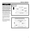
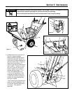
Figure 5-10
N
AV
ZZ
Figure 5-11
A
B
D
E
C
1/16" - 1/8"
1.5 - 3 mm
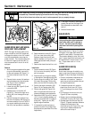
Figure 5-12
N
M
M
20
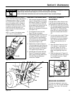
Figure 5-13
AQ
AT
AS
AR
Before inspecting, cleaning or servicing the machine, shut off engine, wait for all moving parts to come to
a complete stop, disconnect spark plug wire and move wire away from spark plug.
Failure to follow these instructions can result in serious personal injury or property damage.
WARNING