


NOTE: Left and right sides of the unit are
determined from the operator position,
facing the direction of forward travel.
A. Inspect Unit
Inspect the unit and shipping crate for
damage immediately after delivery. Contact
the carrier (trucking company) if you find
or suspect damage. Inform them of the
damage and request instructions for filing
a claim. To protect your rights, put your
claim in writing and mail a copy to the car-
rier within 15 days after the unit has been
delivered. Contact the Factory if you need
assistance.
Tools/Materials Required for Assembly
(1) Scissors or knife (to cut plastic ties)
(1) *5/16" wrench
(1) *3/8" wrench
(2) *7/16" wrenches
(2) *1/2" wrenches
(1) *9/16" wrench
(1) Phillips head screwdriver (medium)
(1) Needle-nosed pliers (medium)
(1) Automotive-type tire pressure gauge
(1) Funnel
(1) Clean, high-quality motor oil. Refer to
the separate Engine Owner’s Manual
for the exact oil specifications and
amount needed for your engine.
* Adjustable wrenches may be used.
IMPORTANT: Motor oil must be added to
the engine crankcase before the engine is
started. Follow the instructions in this
Section.
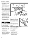
B. Unpack Unit
Follow these steps to unpack your unit.
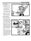
1. After removing cardboard carton, re-
move discharge chute (O, Figure 2-4)
assembly (with attached hardware
bag) from inside cardboard sleeve.
2. Cut plastic ties securing handlebar
ends to chassis and remove handle-
bars. Remove any protective wrapping
on handlebars.
3. Cut the four plastic ties (two on auger
shaft and two on wheel axle) that se-
cure the unit to the shipping pallet.
4. Move unit onto a clean, level surface.
The unit is heavy. To move the unit
off the shipping pallet, use caution
and obtain the help of at least one
assistant.
5. The hardware bag should contain the
following items:
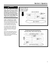
* These are replacement parts (Figure 2-1)
that should be kept with this manual (if the
auger jams, the shear bolts are designed
to break to prevent damage to the auger
drive). See Section 5 for replacement
information.
C. Remove Drift Slicers
(if equipped)
1. Remove the four screws (B, Figure
2-2) and locknuts (two on each side)
that secure the drift slicers (A) and re-
move them from both sides of the col-
lector (auger/impeller) housing.
NOTE: For shipping purposes, the drift
slicers are mounted backwards.
2. Place the drift slicers and hardware
aside. The drift slicers can be attached
after the unit is assembled (see last
step of these assembly instructions).
Description Qty.
Engine Stop Switch Key .................... 1
Plastic Cable Tie ................................ 3
Hex Hd. Flange Screw, 3/8-16 x 3/4 .. 4
Hex Hd. Screw, 1/4-20 x 3/4.............. 2
Locknut, 1/4-20 ................................ 2
Phillips Hd. Screw, #10-24 x 3/8 ...... 2
Locknut, #10-24 ................................ 2
Cotter Pin .......................................... 1
Electric Start Power Cord .................. 1
*Shear Bolt, 5/16-18 x 1-3/4 ............ 2
*Locknut, 5/16-18 ............................ 2
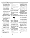
To prevent personal injury or property
damage, do not start the engine until all
assembly steps are complete and you
have read and understand the safety and
operating instructions in this
manual.
WARNING
6
Assembly
2
Section
Figure 2-1
Figure 2-2
B
A
Drift Slicers
(Optional)
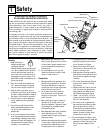
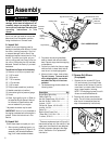
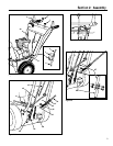
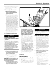
Discharge Chute
Chute
Deflector Cap
Auger Drive Control Lever
Light
Chute Directional Control
Wheel Drive
Control Lever
Auger Assembly
Skid Shoe
Collector
(auger/impeller)
Housing
Gear Shift Lever
FULLY ASSEMBLED UNIT