


Section 2: Assembly
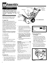
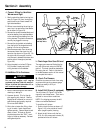
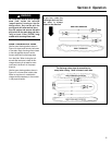
D. Install Handlebars
1. Use the four 3/8-16 x 3/4" hex flange
screws to attach the handlebars to the
sides of the chassis.
a. Install a screw in the upper mount-
ing hole (C, Figure 2-3) on each
side. Leave screws loose enough to
allow handlebar to pivot.
b. Install a screw (D) in the lower
mounting hole on each side.
c. Using light pressure, press down on
the left side handlebar and tighten
the two screws. Repeat on the right
side.
2. There are four pre-installed screws
(E, Figure 2-3) on the inside of the
handlebars that secure the control
panel. Tighten each screw securely.
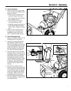
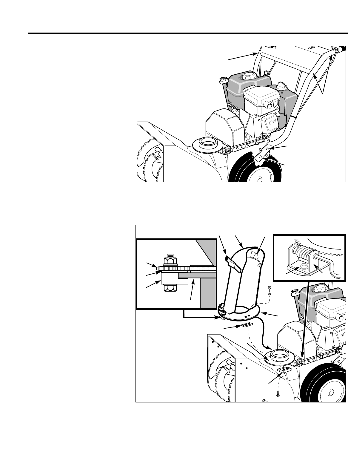
E. Install Discharge Chute
1. Remove the cardboard shield from the
discharge chute mount opening.
2. Loosen (do not remove) the left and
right-side sets of plastic shims (G,
Figure 2-4) and plastic hold-down clips
(H) on the toothed flange (J) of the dis-
charge chute assembly. Remove and
save the remaining (front) hold-down
clip, shim and mounting hardware.
3. From either side of the unit, slide the
discharge chute onto the chute mount-
ing flange (K, Figure 2-4), making sure
that the plastic shims (G) are above
the flange and the plastic hold-down
clips (H) are below the flange. Tighten
the clip mounting hardware securely
(if necessary, rotate the discharge
chute to the right to tighten the left-
side clip).
4. Hook the front hold-down clip (H,
Figure 2-4) under the mounting flange
(K) and place the front plastic shim (G)
on top of the hold-down clip, between
the top of the flange and the toothed
chute flange. Secure with the mount-
ing hardware previously removed.
5. Remove the plastic tie that secures the
worm gear assembly (L, Figure 2-4) to
the mounting bracket.
C
D
E
E
Figure 2-3
Figure 2-4
N
P
O
H
K
L
M
(Front shim) G
(Front hold-
down clip) H
J
K
J
G
7