


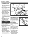
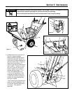
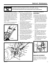
AUGER DRIVE BELT AND WHEEL
DRIVE BELT REPLACEMENT
NOTE: The auger drive belt (there is one
auger drive belt on the 9.5HP model and
two auger drive belts on the 11HP model)
must be removed before removing the
wheel drive belt. The illustration (Figure 5-
6) shows two auger drive belts (AD), ig-
nore the second belt if the unit is not so
equipped.
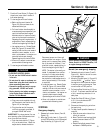
Removal
1. With the engine stopped and the spark
plug wire disconnected, remove the
screws and washers (AB, Figure 5-1)
and remove the belt cover from the
unit.
2. Remove the two screws, flat washers
and lockwashers securing belt guide
(AC, Figure 5-6) to the engine.
Remove the belt guide.
3. Loosen jam nut (BA, Figure 5-6) and
remove bolt (BB).
4. Release tension on the idler (AF,
Figure 5-6). Remove the auger drive
belt(s) (AD) from the auger drive pul-
ley (AE).
5. Remove the auger drive belt(s) from
the lower drive pulley (AO, Figure 5-9)
and remove belt(s) from unit. NOTE: If
you are not replacing the wheel drive
belt (AG), then proceed to Installation.
6. Remove wheel drive belt (AG, Figure
5-6) from lower drive pulley (AH).
Squeeze wheel drive control lever
against handlebar (X, Figure 5-1) to in-
crease gap between lower pulleys as
needed.
7. Remove the wheel drive belt from unit.
Installation
1. Position wheel drive belt (AG, Figure
5-6) into lower drive pulley (AH) clos-
est to the engine.
2. Place the belt into the groove closest
to the engine of the engine pulley (AE).
3. Position auger drive belt(s) (AD, Figure
5-6) down through gap. Position the
belt(s) into the lower drive pulley (AO).
4. Position the auger drive belt(s) (AD,
Figure 5-6) into engine pulley (AE).
5. Position belt guide (AC, Figure 5-6)
back on engine and secure with two
screws and washers removed earlier.
6. Reinstall bolt (BB, Figure 5-6), leaving
1/16" (1.5mm) clearance between un-
derside of bolt head and front edge of
pulley (AE). Tighten jam nut (BA)
against engine crankcase.
7. If the wheel drive belt has been re-
placed, then perform the wheel drive
disc adjustment (see Wheel Drive Disc
Adjustment ).
8. If the auger drive belt(s) have been re-
placed, then perform the Auger Drive
Belt Adjustment as described in this
section.
9. Reinstall the belt cover.
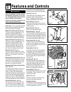
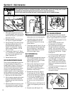
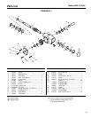
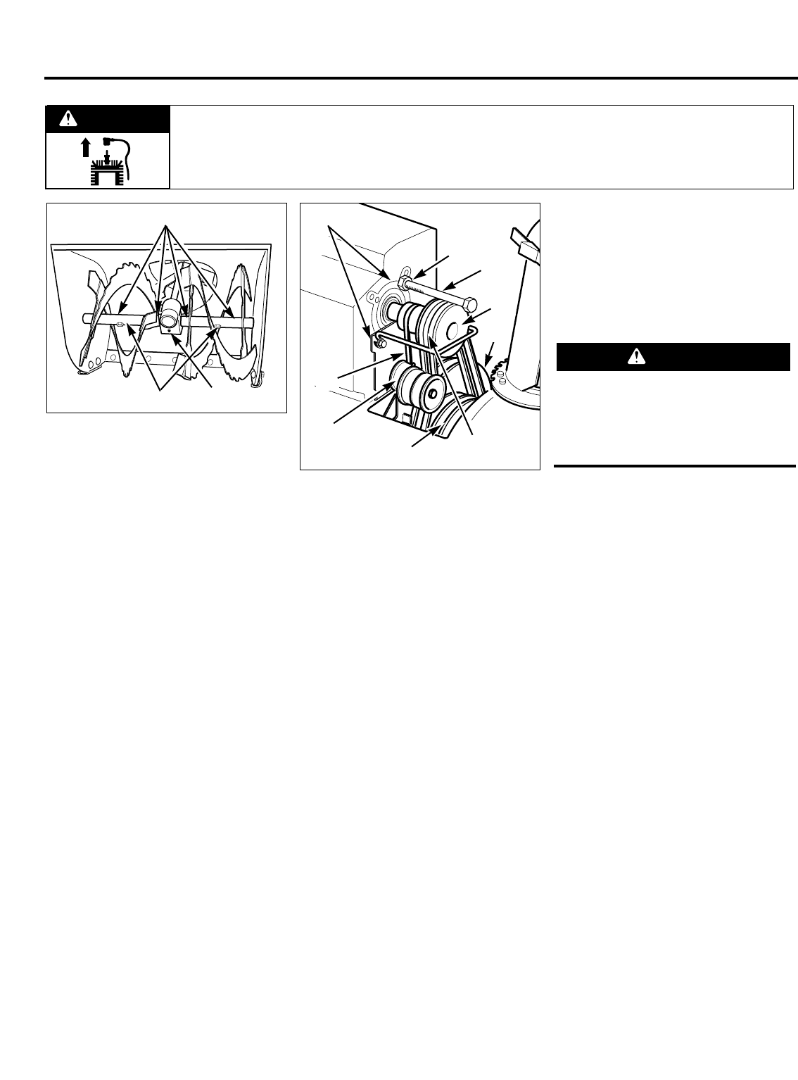
SHEAR BOLTS
Special shear bolts (L, Figure 5-5) secure
the augers to the auger shaft and are de-
signed to break (shear) if the auger jams.
This prevents damage to other, more vital
parts. Inspect shear bolts before each use
and replace them if they are worn or bro-
ken. Torque shear bolts to 11 ft-lbs
(15 Nm).
AUGER DRIVE BELT(S)
ADJUSTMENT
Due to wear, the auger drive belt(s) may
begin to slip when the auger drive lever is
engaged. To adjust the auger drive belt(s):
1. Perform the brake arm adjustment as
described in this section. Leave the
spark plug wire disconnected while per-
forming this adjustment.
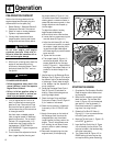
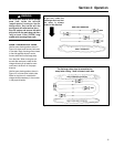
2. If assembling a new unit, raise the
wheel drive control lever (AP, Figure
5-7) and the auger drive control lever
(AL).
3. Pull the auger drive control arm (AJ,
Figure 5-8) down completely.
4. Measure and note distance between
coiled ends of spring (AK, Figure 5-8).
5. Squeeze auger drive control lever (AL,
Figure 5-7) against handlebar. Measure
between the coiled ends of the
stretched spring (AK, Figure 5-8), mak-
ing sure you measure between the
same coils used in step 4.
Section 5: Maintenance
Figure 5-5
Figure 5-6
L
AC
AD
BB
BA
AE
AH
AG
AF
AO
N
M
CAUTION
Using anything but original equipment
shear bolts could result in damage to
the unit. Use factory-specified auger
shaft shear bolts when replacing shear
bolts.
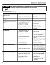
Before inspecting, cleaning or servicing the machine, shut off engine, wait for all moving parts to come to
a complete stop, disconnect spark plug wire and move wire away from spark plug.
Failure to follow these instructions can result in serious personal injury or property damage.
WARNING
18