


31
Section 5: Maintenance
WARNING Before inspecting, cleaning or servicing the unit, shut off engine, wait for all parts to come to a
complete stop, disconnect spark plug wire and move wire away from spark plug. Remove ignition key on elec-
tric start models. Failure to follow these instructions can result in serious personal injury or
property damage.
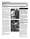
cleaning, coat the terminals with a thin
coat of petroleum jelly or silicone grease
to protect against corrosion.
3. Periodically check the electrical system
for loose or dirty connections.
4. Periodically check that the battery
clamp is tight. However, do not over-
tighten the clamp as doing so could
damage the battery case.
5. Periodically check that the vent tube on
the side of the battery is not crimped or
pinched anywhere along its length.
Battery Storage
The electric start system has a recharging
circuit that will maintain the battery’s state
of charge during the tilling season. When
storing the tiller for extended periods, it is
recommended that the battery be fully
charged before placing it in storage.
(Before reinstalling the battery after
storage, give it a thorough recharge.)
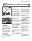
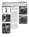
Battery Removal and Installation
When removing and installing the battery,
disconnect and connect the cables in this
order to avoid sparking:
1. To remove the battery, first disconnect
the negative (-) cable from the grounding
screw on the back of the battery bracket
post. Bend the cable away from any metal
parts.
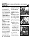
2. Disconnect the negative (-) cable from
the negative (-) battery post.
3. Disconnect the positive (+) cable from
the positive (+) battery post and bend it
away from any metal parts. Cover the
cable terminal with its rubber boot.
4. Remove the battery clamp.
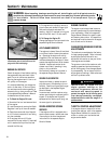
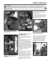
5. To install the battery, reverse the above
steps. Be sure that the battery posts face
to the rear of the tiller and that the positive
(+) post is on the left side as you face
forward from the handlebars.
6. Insert the vent tube into the vent tube
shield. Make sure the vent tube is not
crimped, pinched or folded anywhere
along its length.
TILLER SPECIFICATIONS
TILLER HEIGHT (with Depth Regulator Lever in highest setting):
Without Handlebars .................................................................................24-3/4"
Handlebars in lowest setting.....................................................................39-1/2"
Handlebars in highest setting ...................................................................49-1/2"
TILLER LENGTH
Without Handlebars.................................................................................. 46"
Handlebars in lowest setting..................................................................... 63"
TILLER WIDTH
Hood Width ..............................................................................................16-5/8"
Tilling Width ............................................................................................. 16"
Wheel Width.............................................................................................18-3/4"
Handlebar Width.......................................................................................20-1/4"
TILLER WEIGHT
Approximate Weight (without oil or gas):
Recoil Start Model.................................................................................172 lbs.
Electric Start Model ...............................................................................178 lbs.
TRANSMISSION GEAR OIL SPECIFICATIONS
For small top-offs: Use SAE 140, SAE 85W-140, or SAE 80W-90 gear oil with an
API rating of either GL-4 or GL-5.
For Full Replacement: Use SAE 140 or SAE 85W-140 gear oil with API rating of
GL-4 (do not use GL-5).
TILLER ATTACHMENTS
The attachments listed below are available for your tiller. The information is the
most current at the time this manual was printed. Contact your authorized dealer or
the factory for current information.
BUMPER
The tubular steel bumper surrounds the engine to protect the air cleaner, starter
assembly and fuel tank from damage.
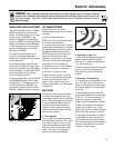
HILLER/FURROWER
The furrower blade attaches to the back of the depth regulator assembly and is
used to create rows, trenches and ditches up to 8" deep, depending on soil con-
ditions. The two hiller wings attach to the sides of the furrower blade and are
used to make hilled rows and raised bed gardens.
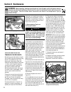
ROW MARKER
The row marker attaches to the hiller/furrower attachment and is used to scratch
lines in the seedbed for laying out furrows, trenches, raised beds, etc. (elimi-
nates the need for stakes, string and measuring tape). The row marker is
adjustable in length from 28" to 49-3/4", allowing you to vary the width of the
marked rows as required.