


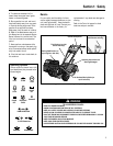

6
Introduction
Carefully follow these assembly steps to
correctly prepare your tiller for use. It is
recommended that you read this Section
in its entirety before beginning assembly.
Inspect unit
Inspect the unit and carton for damage
immediately after delivery. Contact the
carrier (trucking company) if you find or
suspect damage. Inform them of the
damage and request instructions for filing
a claim. To protect your rights, put your
claim in writing and mail a copy to the
carrier within 15 days after the unit has
been delivered. Contact us at the factory if
you need assistance in this matter.
STEP 1: Unpacking Instructions
1. Remove any cardboard inserts and
packaging material from the carton.
Remove any staples from the bottom of
the carton and remove the carton.
2. Remove the handlebars from the
carton. To avoid damaging parts, do not
uncoil any cables until instructed to do so.
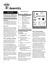
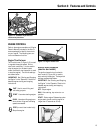
3. A bag with loose hardware is inside the
literature envelope. Check the contents
against the following list and Figure 2-1.
Contact your local dealer or the factory if
any items are missing or damaged.
NOTE: For electric start units, a second
hardware bag is located near the battery.
The parts in that bag are described later
in this Section.
4. The tiller is heavy and you should not
attempt to remove it from the shipping
platform until instructed to do so in these
“Assembly” steps.
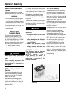
Hardware Bag Parts List
Fig.
Ref. Qty. Description
1 1 Height Adjustment Handle
2 1 Keyed Washer
3 3 Hairpin Cotter (one spare)
4 2 3/8-16 x 1" Hex Hd. Screw
5 2 3/8" Flat Washer
6 2 3/8"-16 Nylock Lock Nut
7 1 Throttle Lever Knob
8 1 Wheel Gear Lever Knob
9 4 #10-32 x 1/2" Round Hd.
Screw
10 4 #10 Lockwasher
11 4 #10-32 Nut
12 4 Plastic Tie Strap
13 1 Cotter Pin (not used on unit)
Tools/Materials Needed
for Assembly
(1) 3/8" open-end wrench*
(1) 7/16" open-end wrench* (electric
start unit only)
(2) 9/16" open-end wrench*
(1) 7/8" open-end wrench or 8" long
adjustable wrench
(1) Scissors (to trim plastic ties)
(1) Ruler
(1) Small board (to tap plastic knobs on
levers)
(1) Tire pressure gauge
(1) Clean oil funnel
(1) Clean, high-quality motor oil. Refer
to the separate Engine Owner’s
Manual for motor oil specifications
and quantity required.
* Adjustable wrenches may be used.
IMPORTANT: Motor oil must be added to
the engine crankcase before the engine is
started. Follow the instructions in this
“Assembly” Section and in the separate
Engine Owner’s Manual.
NOTE: LEFT and RIGHT sides of the tiller
are as viewed from the operator’s posi-
tion behind the handlebars.
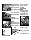
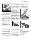
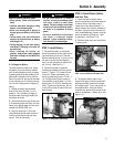
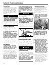
STEP 2: Attach Handlebars
1. On electric start units, remove one
screw and lockwasher from the curved
height adjustment bracket (A, Figure 2-2),
loosen the second screw, and swing the
bracket to one side.
2. Place the handlebar cross-brace (B,
Figure 2-3) in front of the curved height
adjustment bracket (C) and position the
handlebar ends on the outside of the two
mounting tabs on the transmission cover.
3. Loosely attach the handlebars to the
mounting tabs with two 3/8-16 x 1"
screws (heads of screws go to inside of
tabs), 3/8" flat washers and 3/8"-16
Nylock lock nuts (see D, Figure 2-3).
4. On electric start units, reattach the
height adjustment bracket (A, Figure 2-2).
Tighten both screws securely.
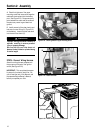
5. Move the handlebars up or down to
align the hole in the cross-brace with one
of the four slots in the curved height
adjustment bracket. Place the keyed
washer (E, Figure 2-4) on the height
adjustment handle (F) with the raised
keys (edges) on the washer facing down.
Section
2
Assembly
Figure 2-1: Loose hardware (see parts list).
1
2
3
4
5
6
7
13
8
9
10
11
12
To prevent personal injury or property
damage, do not start the engine until all
assembly steps are complete and you
have read and understand the safety and
operating instructions in this Manual.
WARNING