


7
Section 2: Assembly
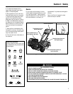
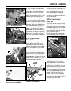
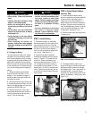
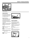
6. Screw the height adjustment handle
(F) into the hole in the handlebar cross-
brace, making sure that the raised keys
on the washer fit into the slot on the
height adjustment bracket. Tighten the
height adjustment handle securely. Next,
securely tighten the two screws in the
ends of the handlebars (D, Figure 2-3).
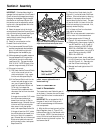
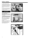
7. To remove the tiller from its shipping
platform, first carefully unwrap the wheel
gear cable (G, Figure 2-5) from around
the chassis. Next, move the Wheel Gear
Lever to the DISENGAGE position (this
allows the wheels to rotate). Use the han-
dlebars to roll the tiller off the platform.
IMPORTANT: Use the DISENGAGE posi-
tion only when the engine is not running.
Before starting the engine, the Wheel
Gear Lever must be placed in the ENGAGE
position (see Section 3 for details).
STEP 3: Attach Reverse
Clutch Control
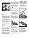
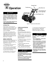
1. Carefully unwrap the Reverse Clutch
Control cable (H, Figure 2-6) from its
shipping position and route it up along
the inside edge of the left side handlebar.
A knob and large hex nut (I) is installed
on the cable.
2. Insert the cable into the slot in the
control panel and fit the threaded assem-
bly into the hole in the slot (see Figure 2-
6). Be sure that the flat side of the
threaded assembly is aligned with the flat
side of the hole. Slide the hex nut (I) up
the cable and tighten it securely.
3. Test the function of the reverse clutch
cable by pulling the knob out and releas-
ing it. The knob should return to its
neutral position against the tapered
bushing when it is released. If it doesn’t,
contact your local dealer or the factory for
technical assistance.
STEP 4: Attach Forward
Clutch Rod
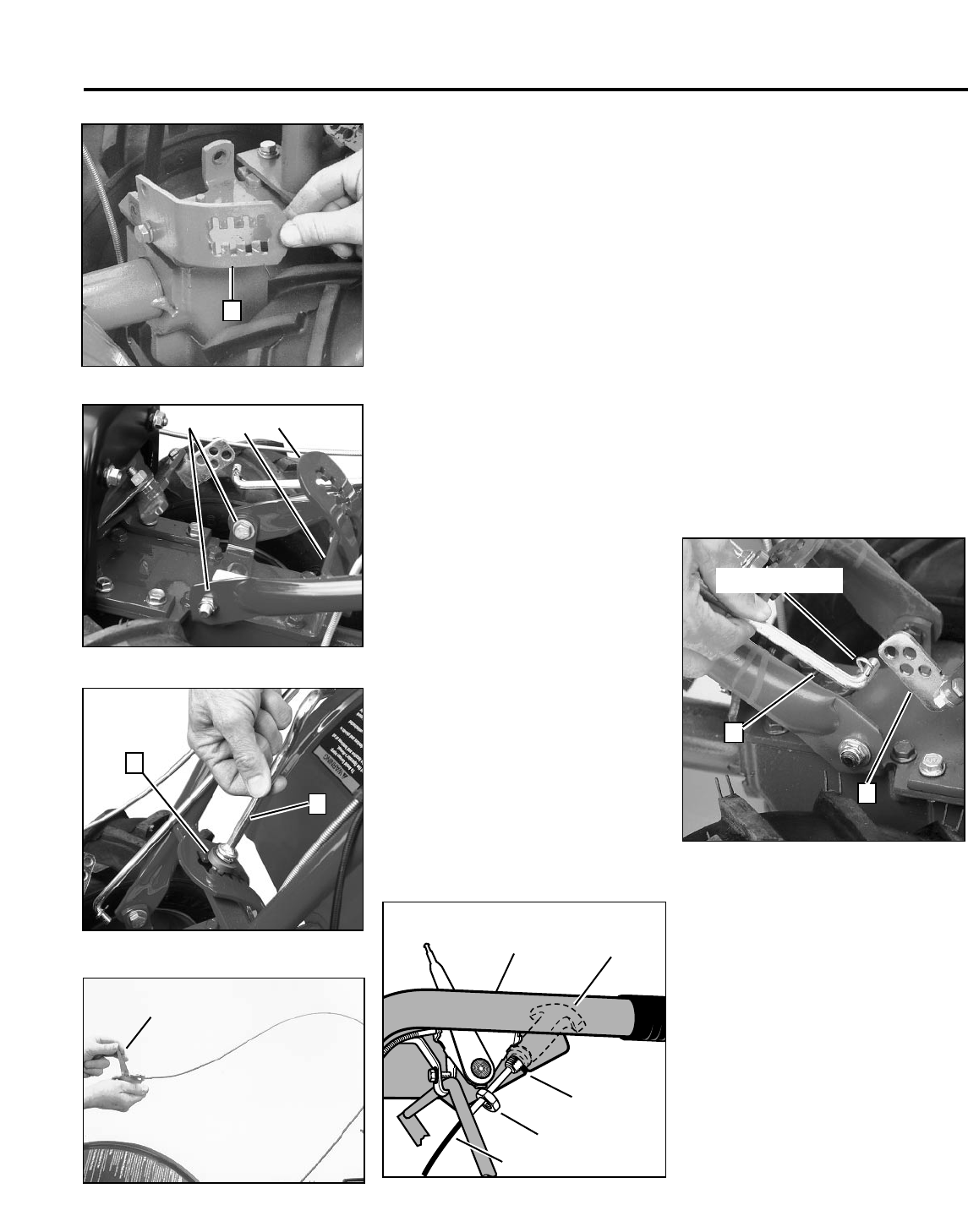
1. The upper end of the Forward Clutch
rod is connected to the two Forward
Clutch levers (paddles) that hang below
the handlebar grips. Turn the lower end of
the rod (J, Figure 2-7) so that the angled
end points inward toward the outer face
of the clutch swivel plate (K).
2. Insert a hairpin cotter down through
the innermost hole in the rod (Figure 2-7).
3. There are four holes in the clutch
swivel plate and four slots in the curved
height adjustment bracket (see numbered
holes and slots in Figure 2-8). For correct
operation of the Forward Clutch rod, the
numbered hole used for the Forward
Clutch rod must match with the numbered
slot in the height adjustment bracket. For
example, if the Forward Clutch rod is
installed in hole #1 of the clutch swivel
plate, then the handlebar height adjust-
ment handle must be installed in slot #1 of
the height adjustment bracket.
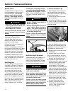
Figure 2-2: Move height bracket aside.
Figure 2-3: Attach handlebars.
Figure 2-4: Install height adjustment handle.
C
B
D
E
F
A
Figure 2-5: Carefully unwrap Wheel Gear
Lever and move lever to DISENGAGE.
➥
G
Figure 2-6: Attach Reverse Clutch Control to
slotted hole in handlebar panel.
I
H
Left Side
Handlebar
Knob
Slot in
Control
Panel
Figure 2-7: Install Forward Clutch rod.
J
Hairpin Cotter
K