


27
WARNING Before inspecting, cleaning or servicing the unit, shut off engine, wait for all parts to come to a
complete stop, disconnect spark plug wire and move wire away from spark plug. Remove ignition key on elec-
tric start models. Failure to follow these instructions can result in serious personal injury or
property damage.
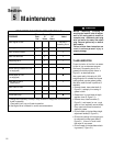
Section 5: Maintenance
To Check and Adjust Tension on
the Reverse Drive Belt
1. Remove the belt cover (E, Figure 5-8)
after first shutting off the engine, discon-
necting the spark plug wire, removing the
ignition key on electric start models, and
allowing the engine and muffler to cool
down.
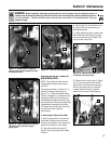
2. Have an assistant pull the Reverse
Clutch Control knob all the way out and
hold it in that position. Measure the
length of the cable wire between the end
of the threaded cable adjuster (K, Figure
5-12) and the end of the Z-fitting (L) to
which the cable wire is attached.
3. The belt tension is correct if the cable
wire length measures between 1/8" to 1/4".
If the length is less than 1/8" (and if there
is no reverse action when the tiller is
running), then make the following adjust-
ments. NOTE: If the length is more than
1/4", no adjustment is needed, as long as
the reverse action functions properly.
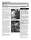
4. Release the Reverse Clutch control
knob. Unthread the inner jam nut (M,
Figure 5-13) one to two turns and pull the
threaded cable adjuster (K) to the left until
the inner jam nut rests against the
bracket.
5. Prevent the inner jam nut (M) from
turning and tighten the outer jam (N)
against the bracket. Prevent the outer
jam nut (N) from turning and tighten the
inner jam nut (M) against the bracket.
6. Measure the gap by repeating Step 2.
Readjust as needed by repeating Steps 4
and 5.
7. Reinstall the belt cover and secure it
with the two nuts.
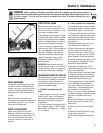
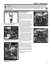
Figure 5-9: One or two threads on Forward
Clutch Rod should show above nut.
D
Threads
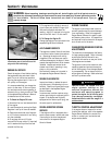
Figure 5-10: Remove clevis pin from outer
hole in forward adjustable link and move to
inner hole in link.
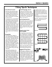
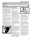
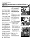
Figure 5-11: View of belts and pulleys.
Only the upper half of the transmission
pulley (S) is shown.
G
I
P
T
S
J
H
F
R
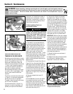
Figure 5-12: Measure length of cable.
L
K
Figure 5-13: Adjust jam nuts.
K
M
N