


9
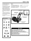
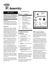
Section 2: Assembly
STEP 6: Add Motor Oil to Engine
The tiller is shipped without oil in the
engine.
IMPORTANT: Do not start the engine
without first adding motor oil. Severe
engine damage will result if the engine is
run without oil.
1. Refer to the separate Engine Owner’s
Manual for motor oil specifications and
capacities.
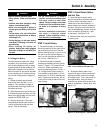
2. With the unit on level ground, move
the Depth Regulator Lever (L, Figure 2-
10) up or down until the engine is level.
3. Add motor oil as described in the
Engine Owner’s Manual.
4. Move the Depth Regulator Lever all
the way down until the highest notch is
engaged. This places the tines in the
“travel” position.
STEP 7: Attach Engine Throttle
Lever
1. Carefully unwrap the engine throttle
cable assembly from around the engine
and route it up the right-side handlebar.
2. Insert the Throttle Lever (O, Figure 2-
13) up through the slot in the control
panel that is labeled “ENGINE THROTTLE.”
3. Insert two #10-32 x 1/2" round head
screws down through the “+” marks on
the control panel decal and securely
attach the throttle lever mounting bracket
using two #10 lockwashers and #10-32
nuts.
4. Using a board, tap the “T” shaped
knob securely onto the lever (see Figure
2-13).
5. Move the lever fully forward and back-
ward. On recoil start models, it should
move freely from the “FAST” to the
“STOP” settings. On electric start
models, it should move freely from the
“FAST” to the “SLOW” settings.
(Note that there is a detent setting which
will catch the lever before it reaches the
“STOP” [recoil start model] or “SLOW”
[electric start model] settings.)
If the lever is difficult to move away from
the “STOP” (recoil start model) or
“SLOW” (electric start model) settings,
loosen both bracket screws, move the
lever assembly slightly to the left, and
retighten both screws. Recheck the lever
movement and readjust as needed.
6. Secure the throttle cable to the right-
side handlebar with two plastic ties (R,
Figure 2-14) located about two feet apart.
The serrated side of the tie should be on
the inside of the loop. Snip off any
excess tie length with scissors.
STEP 8: Attach Wheel Gear Lever
1. Carefully unwrap the wheel gear cable
from around the transmission and route
the cable up the left-side handlebar.
2. Insert the Wheel Gear Lever (P, Figure
2-15) up through the slot in the control
panel that is labeled “WHEEL GEAR.”
3. Insert two #10-32 x 1/2" round head
screws down through the “+” marks on
the control panel decal and securely
attach the wheel gear mounting bracket
using two #10 lockwashers and #10-32
nuts.
4. Using a board, tap the Wheel Gear
Lever knob securely onto the lever (see
Figure 2-15).
5. Secure the wheel gear cable and the
reverse clutch cable to the left-side han-
dlebar with two plastic ties (S, Figure
2-14) located about two feet apart. Snip
off any excess tie length with scissors.
STEP 9: Check Air Pressure
in Tires
Use a tire pressure gauge to check the air
pressure in both tires. Deflate or inflate
both tires equally to 15-to-20 PSI
(pounds per square inch). Be sure that
both tires are inflated equally or the unit
will pull to one side.
STOP
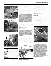
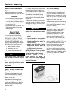
Figure 2-12: Adding gear oil.
N
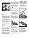
Figure 2-13: Attach engine throt-
tle lever.
O
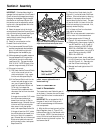
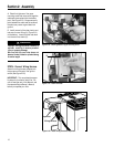
Figure 2-14: Attach throttle cable with cable
ties (R). Attach wheel gear cable and
reverse clutch cable with cable ties (S).
Figure 2-15: Attach Wheel Gear Lever.
S
R
P