


Section 5: Maintenance
26
WARNING Before inspecting, cleaning or servicing the unit, shut off engine, wait for all parts to come to a
complete stop, disconnect spark plug wire and move wire away from spark plug. Remove ignition key on elec-
tric start models. Failure to follow these instructions can result in serious personal injury or
property damage.
CHECKING AND ADJUSTING
TENSION ON THE DRIVE BELTS
Maintaining correct belt tension is impor-
tant to good tilling performance and long
belt life. A loose belt will slip on the
engine and transmission pulleys and
cause the tines and wheels to slow down
– or stop – even though the engine is
running at full speed. A loose belt will
also result in premature belt wear.
While checking belt tension, also check
for cracks, cuts or frayed edges. A belt
that is in poor condition should be
replaced.
The tension on a new forward drive belt
(I, Figure 5-11) should be checked after
the first two (2) hours of operation.
Thereafter, check the tension after every
ten (10) hours of operation.
The reverse drive belt (J, Figure 5-11),
because it is used more sparingly, will
probably not require an initial tension
adjustment until a significant number of
operating hours has passed. A tension
adjustment is required only if there is no
reverse action when the Reverse Clutch
Control knob is pulled out.
To Check and Adjust Tension on
the Forward Drive Belt
1. The check for correct belt tension is
the same as that described in item 5 of
“Step 4: Attach Forward Clutch Rod” on
page 8. Before performing this check,
shut off the engine, disconnect the spark
plug wire, remove the ignition key on
electric start models, and allow the
engine and muffler to cool down. If, after
following the adjustment procedures you
cannot get the correct gap on the forward
clutch rod adjustment bracket, you will
need to make a secondary adjustment as
described next.
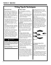
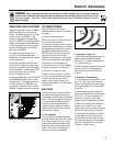
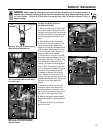
2. Disconnect the Forward Clutch Rod (A,
Figure 5-8) from the swivel plate (B) by
removing the innermost hairpin cotter (C).
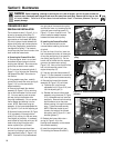
3. Unthread the Forward Clutch Rod (in a
counterclockwise direction as viewed
from the front of the unit) until one or two
threads on the rod extend above the rect-
angular nut (D, Figure 5-9) on the forward
clutch bracket.
4. Remove the plastic belt cover (E,
Figure 5-8).
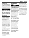
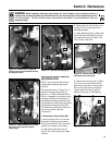
5. On the left side of the unit (as viewed
from operator’s position) remove the
hairpin cotter from the clevis pin (F, Figure
5-10) that connects the forward idler arm
(G) to the forward adjustable link (H).
Push inward on the forward idler arm (G)
and remove the clevis pin (F).
6. There are two holes in the forward
adjustable link (H, Figure 5-10). Push
inward on the forward idler arm (G) and
install the clevis pin (F) through the inner
hole in the forward adjustable link (H) and
out through the single hole in the forward
idler arm (G). Secure the clevis pin with
the hairpin cotter. NOTE: While pushing
inward on the forward idler arm, be sure
that the forward drive belt is moved off to
the right side of the tiller. This creates
more room to install the clevis pin when
the forward idler arm is pushed inward.
IMPORTANT: With the clevis pin installed
in the inner hole of the forward adjustable
link, the number of additional belt tension
adjustments that can be made is limited.
If, with future tension adjustments, you
find that you cannot screw the forward
clutch rod any farther into the rectangular
nut on the forward clutch bracket, it
means that the forward drive belt must be
replaced. Before doing so, the clevis pin
must be returned to the OUTSIDE hole in
the forward adjustable link.
7. Reinstall the belt cover and secure it
with the two nuts.
8. Readjust the forward drive belt tension
by following the “Handlebar Height
Adjustment” instructions in Section 3.
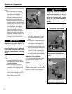
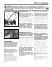
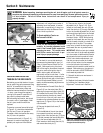
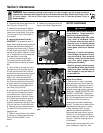
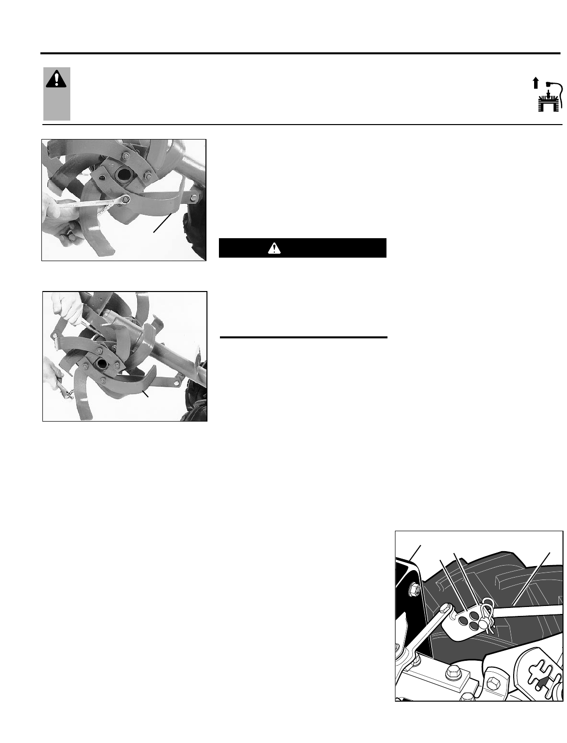
Figure 5-6: Removing single tine.
Figure 5-7: Removing a tine assembly.
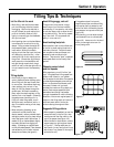
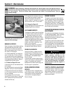
Cutting Edge
of Tine
Cutting Edge
of Tine
Follow the belt adjustment instructions
carefully. An incorrect adjustment could
result in the Forward Clutch mechanism
engaging too soon. This could cause
loss of tiller control and result in per-
sonal injury or property damage.
WARNING
Figure 5-8: Disconnect Forward Clutch Rod
and move forward drive belt out of groove
in engine forward drive pulley
A
B
E
C