


- 11 -
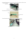
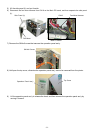
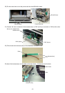
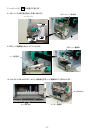
16) Remove the Expansion I/O board from the printer temporarily using the following procedure.
(1) Disconnect the Expansion I/O cable from CN1 on the Expansion I/O board.
(2) Remove the two B-3x6 screws to detach the Expansion I/O board from the printer.
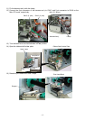
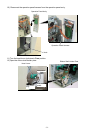
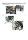
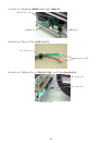
17)
Disconnect the shorter harness of the strip sensor harness (TR) from CN20 on the Main PC board.
Then remove the strip sensor (TR) from the printer.
NOTE:
Retain the strip sensors (TR) and (LED), and the strip sensor harness.
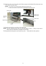
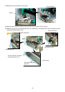
18)
Disconnect the longer harness of the rewind full sensor (TR) and rewinder harness from CN4 and CN15
on the Main PC board, respectively.
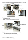
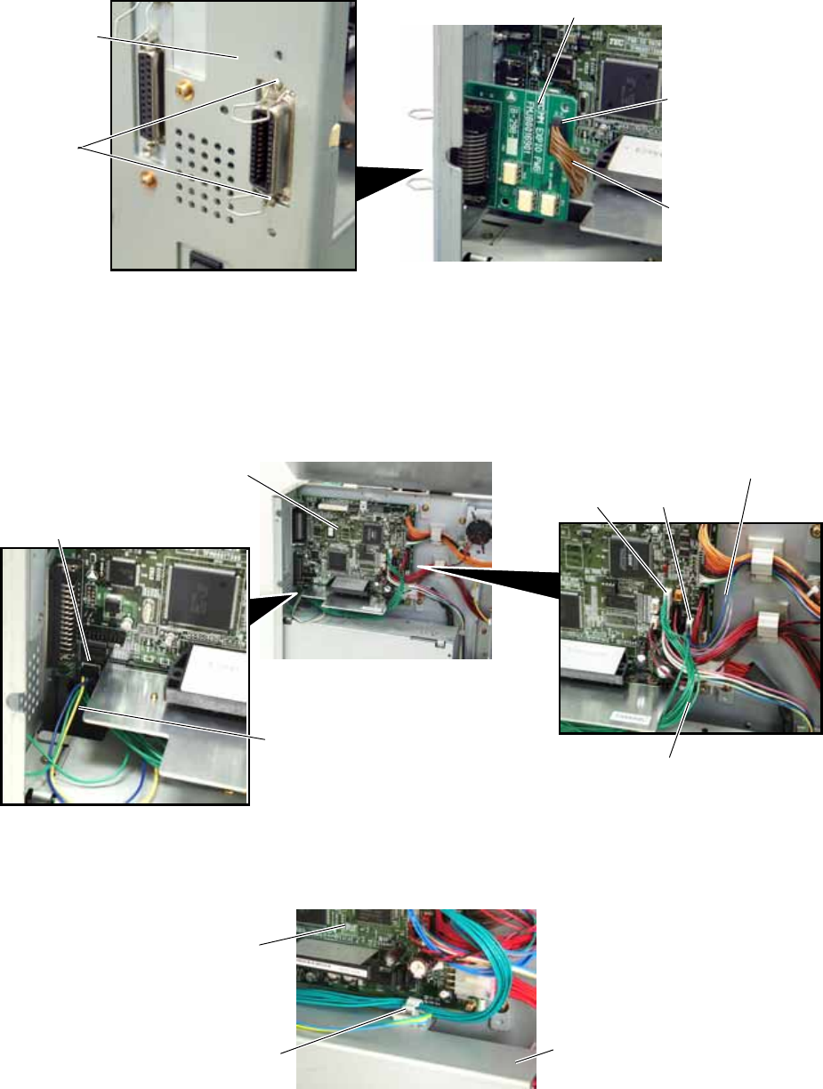
NOTE:
Secure the rewinder harness and the longer harness of the rewind full sensor (TR) to the space
under the Main PC board with the cable clamp so that they are not pinched by the covers or
printer’s internal components.
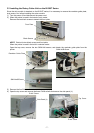
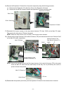
19)
Reassemble the operation panel ass’y and the expansion I/O board in the reverse order of removal.
CN1
Expansion I/O Board
Expansion I/O Cable
B-3x6 Screw
Rear Plate
Main PC Board
Longer Harness of the
Rewind Full Sensor (Tr)
CN4
CN15
Rewinder Harness
CN20
Shorter Harness of the
Strip Sensor Harness (Tr)
Cable Clamp
Main PC Board
PS Unit