20
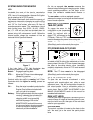
d. Insert the shoulder screw with the rear gauge
wheel into the index hole that leaves
approximately 1/2" between the bottom of
the wheel and the pavement.
e. Note the position of the index hole used; then
install the other rear gauge wheel and the
front ball wheels into the corresponding index
hole of the other gauge wheel brackets.
• If the gauge wheels have excessive clearance with
the surface below, lower the wheels to the index
hole that provides the approximate 1/2" clearance
as described above.
Roller (Model GT2300)
To adjust the height of the rollers found on the rear of
the mowing deck upward or downward, proceed as
follows:
• Place the deck lift lever in the lowest position.
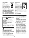
• Remove the clevis pins and hairpin clips from the
deck roller brackets on the left and right sides of the
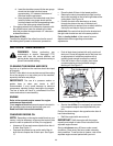
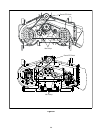
cutting deck. See Figure 16.
• Position the deck roller brackets up or down
through the slots on the rear of the deck until
desired position is reached, then re-attach with the
clevis pins and hairpin clips just removed.
IMPORTANT:
Be certain that the left roller bracket and
the right roller bracket are set in the same position.
Refer to Leveling the Deck of this manual for more
detailed instructions regarding various deck
adjustments.
SECTION 8: MAINTENANCE
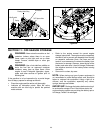
WARNING: Before performing any
maintenance or repairs, disengage PTO,
move shift lever into neutral position, set
parking brake, stop engine and remove key to
prevent unintended starting.
CLEANING THE ENGINE AND DECK
Any fuel or oil spilled on the machine should be wiped
off promptly.
Do NOT allow debris to accumulate around the cooling
fins of the engine or on any other part of the machine,
especially the belts and pulleys.
IMPORTANT: The use of a pressure washer or
garden hose to clean your tractor is NOT
recommended. It may cause damage to electrical
components, spindles, pulleys, bearings or the engine.
The use of water will result in a shortened life of the
tractor and reduce its serviceability.
ENGINE
Refer to the separate engine manual for engine
maintenance instructions.
Check engine oil level before each use as instructed in
the separate engine manual packed with your unit.
Read and follow instructions carefully.
CHANGING ENGINE OIL
NOTE:
Depending on the engine model found on your
tractor, it may be necessary to remove the tractor’s side
panel in order to replace the oil filter (if so equipped).
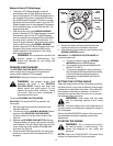
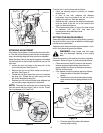
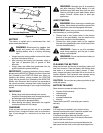
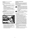
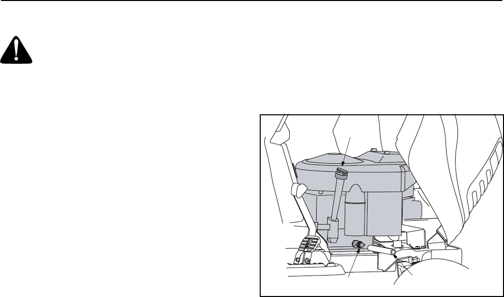
• Unscrew oil fill cap and remove dipstick from the oil
fill tube. See Figure 17.
• Pop open the protective cap on the end of the oil
drain valve to expose the oil drain port. See Figure
17.
• Push oil drain hose (packed with unit) onto the oil
drain port. Route the opposite end of the hose into
an appropriate oil collection container with a
capacity great enough to collect the used oil.
• Push the oil drain valve in slightly, then rotate
counterclockwise and pull outward to begin
draining oil. See Figure 17.
Figure 17
• Service the oil filter (if so equipped) as instructed
in the separate engine manual packed with your
unit.
Perform the above steps in the opposite order after oil
has finished draining.
• Refill the engine with new motor oil.
IMPORTANT: Refill the engine with the proper
capacity and weight of motor oil as instructed in the
separate engine manual.
Service air cleaner every 25 hours under normal
conditions. Clean every few hours under extremely
dusty condition. To service the air cleaner, refer to the
separate engine manual packed with your unit.
Oil Fill Cap Dipstick
Oil Drain Hose
Drain Port


