


19
•
•
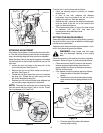
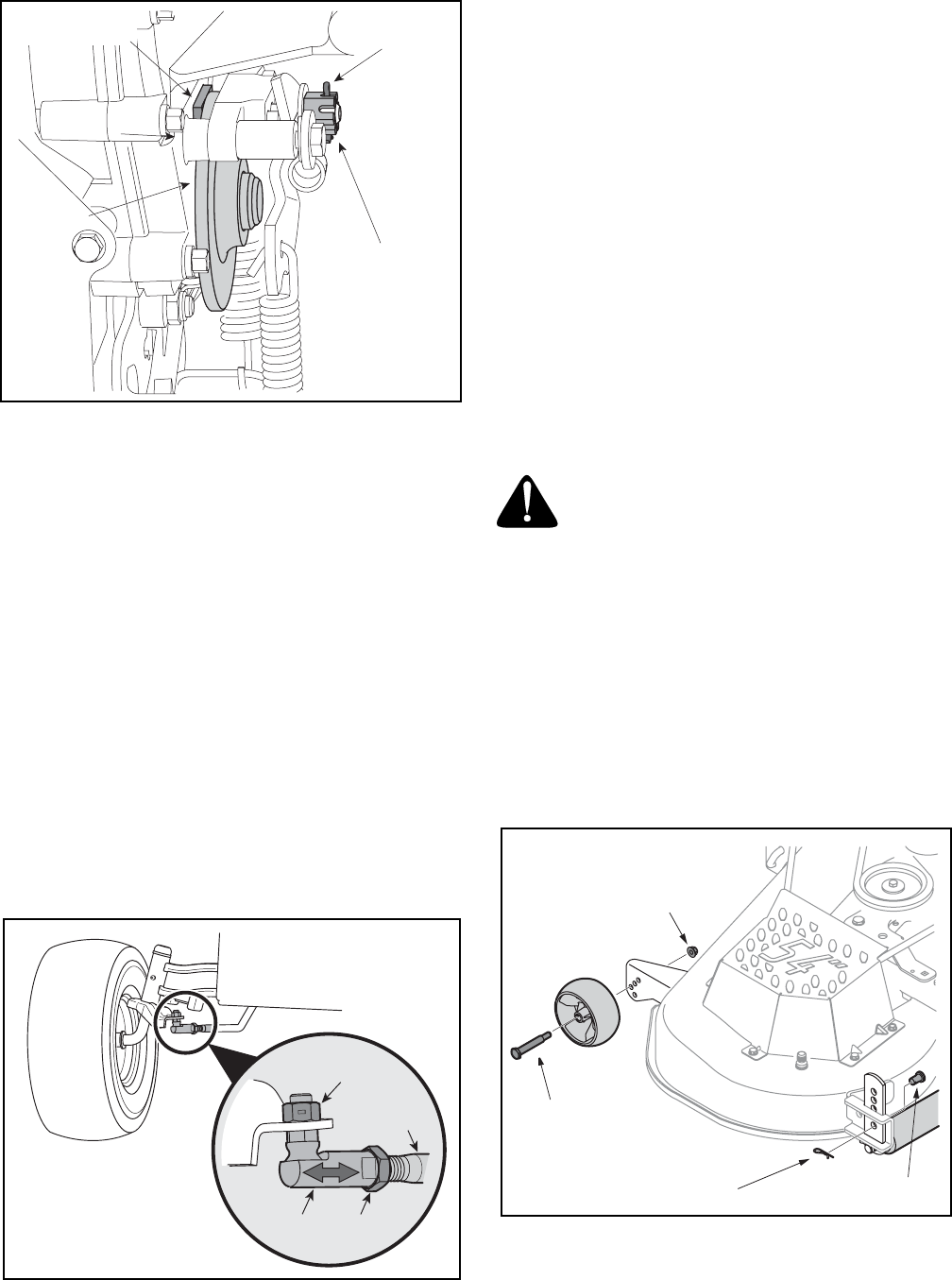
Figure 14
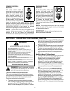
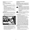
STEERING ADJUSTMENT
If the tractor turns tighter in one direction than the other,
or if the ball joints are being replaced due to damage or
wear, the steering drag links may need to be adjusted.
Adjust the drag links so that equal lengths are threaded
into the ball joint on the left side and the ball joint on the
right side:
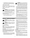
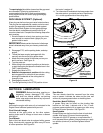
• Loosen the jam nut found on the drag link at the
rear of the ball joint. See Figure 15.
• Remove the hex nut and lock washer on the top of
ball joint. See Figure 15.
• Thread the ball joint toward the jam nut to shorten
the drag link. Thread the ball joint away from the
jam nut to lengthen the drag link.
• Replace hex nut and lock washer and retighten the
jam nut after proper adjustment is achieved.
NOTE: Threading the ball joints too far onto the drag
links will cause the front tires to "toe-in" too far. Proper
toe-in is between 1/16" and 5/16".
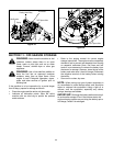
Figure 15
Front tire toe-in can be measured as follows:
• Place the steering wheel in position for straight
ahead travel.
• In front of the axle, measure the distance
horizontally from the inside of the left rim to the
inside of the right rim. Note the distance.
• Behind the axle, measure the distance horizontally
from the inside of the left rim to the inside of the
right rim. Note the distance.
• The measurement taken in front of the axle should
be between 1/16" and 5/16" less than the
measurement taken behind the axle.
• Adjust if necessary.
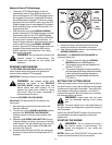
SETTING THE GAUGE WHEELS
Select the height position of the cutting deck by placing
the deck lift lever in any of the six different cutting height
notches on the right fender.
Adjust the deck wheels so that they are between ¼-inch
and ½-inch above the ground as follows.
WARNING: Keep hands and feet away
from the discharge opening of the cutting
deck.
Place the tractor on a firm and level surface, preferably
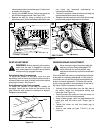
pavement. Refer to Figure 16, and proceed as follows:
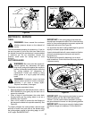
• Place the tractor’s deck lift handle in the normally
desired mowing height setting, then check the
gauge wheels for contact or excessive clearance
with the surface below.
• If the wheels contact the surface adjust as follows:
a. Raise the deck lift handle to its highest
setting.
b. Remove the lock nuts and shoulder screws
which secure the front gauge wheels to the
deck.
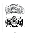
Figure 16
c. Place the deck lift handle in the desired
mowing height setting.
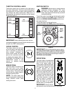
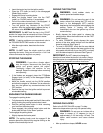
Crown Nut
Cotter Pin
Brake Disc
Brake Puck
Brake Puck
Brake Puck
Brake PuckBrake PuckBrake PuckBrake Puck
Brake Puck
Brake Puck
Brake PuckBrake Puck
Hex Nut
Jam
Nut
Ball
Joint
Drag Link
Cotter Pin
Lock Nut
Shoulder Screw
Clevis Pin