


Reelmaster 2300–D/2600–D Hydraulic SystemPage 4 – 55
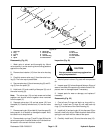
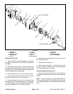
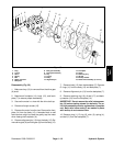
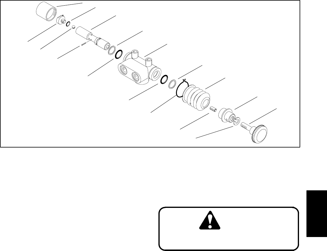
1. Valve cap
2. Plug
3. O–ring
4. Ball
5. Spool
6. Spring pin
7. Back–up ring
8. O–ring
9. Valve housing
10. Boot retainer
11. Boot
12. Set screw
13. Valve stop
14. Lock washer
15. Knob
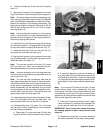
Figure 52
1
3
5
7
9
7
11
13
15
2
4
6
8
8
10
12
14
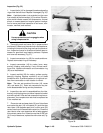
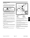
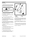
Disassembly (Fig. 52)
1. Wash valve in solvent and thoroughly dry. Mount
valve carefully in a vise ensuring the mounting pads are
against the vise jaws.
2. Remove boot retainer (10) from the valve housing
(9).
3. Carefully remove valve cap (1) from the valve hous-
ing (9). The valve cap is press fitted.
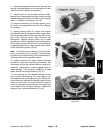
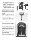
4. Secure valve stop (13) and remove plug (2) and O–
ring (3) from the spool (5).
5. Hold knob (15) and carefully slide spool (5) out of
the valve housing (9).
Note: The valve stop (13) and set screw are loctited
together and should remain together when removed
from the spool (5).
6. Separate valve stop (13) and set screw (12) from
the spool (5). Carefully remove boot (11) from the valve
stop.
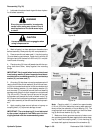
7. Remove spring pin (6) and ball (4) from the spool (5)
being careful no to scratch or damage the spool. Also,
be careful not to drop the ball.
8. Remove back–up rings (7) and O–rings (8) from the
valve housing with a hooked scribe or thin screw driver.
Be careful not to scratch the bore surface.
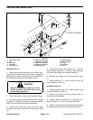
Inspection (Fig. 52)
CAUTION
Use eye protection such as goggles when
using compressed air
1. Wash all parts in solvent. Dry parts with compressed
air.
2. Inspect spool (5) for bending and flatness. Signs of
wear on one side of the spool may indicate it’s bent. Re-
place a worn or damaged spool if necessary.
3. Inspect parts for wear or damage, and replace if
necessary.
Reassembly (Fig. 52)
1. Coat all new O–rings and back–up rings with hy-
draulic oil. Install new O–rings (8) and new back–up
rings (7) into the bore of the valve housing (9).
2. Install ball (4) and spring pin (6) into the spool (5) so
the ball is held in by the pin. Make sure both ends of the
spring pin are flush with the sides of the spool.
3. Carefully install boot (12) onto the valve stop (13).
Hydraulic
System