Reelmaster 2300–D/2600–D Page 7 – 15 Cutting Units
Note: On rear counterbalance spring, make sure that
the vinyl cover is on prior to reinstalling the spring.
4. Make sure one end of spring is secured to the spring
shackle and the other end is hooked into the lift tab hole
noted in step 6.
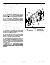
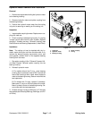
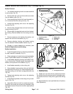
5. Secure counterbalance spring and lift tab to the car-
rier frame with the capscrews and lock washers (Fig.
16).
6. Insert a breaker bar into the square hole in the coun-
terbalance arm, and pivot the counterbalance arm back
to its original position aligning the cap screw hole (fig.
15).
7. Secure bottom of counter balance arm to frame with
the bottom capscrew. Tighten top cap screw (Fig. 15)
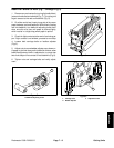
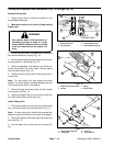
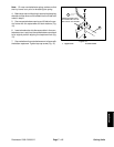
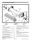
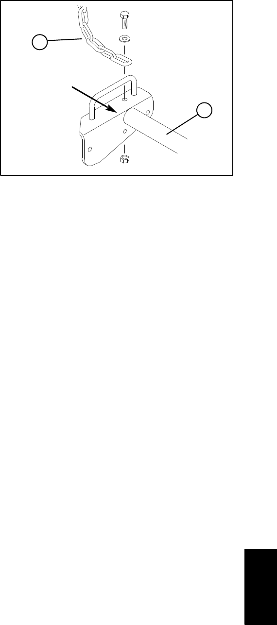
1. Tipper chain 2. Carrier frame
Figure 18
1
2
RM2600 TIPPER CHAIN
IS CONNECTED TO THE
BOTTOM OF THE FRAME
Cutting Units


