


Reelmaster 2300–D/2600–DHydraulic System Page 4 – 44
Wheel Motor
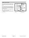
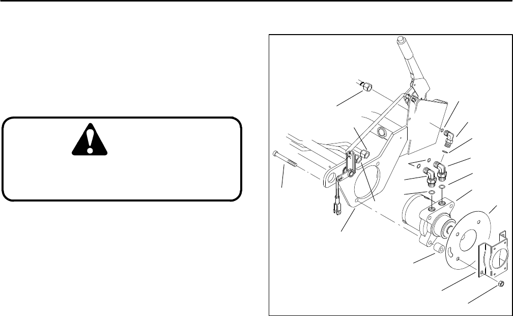
Front Wheel Removal (Fig. 30)
1. Before removing any parts from the hydraulic sys-
tem, park the machine on a level surface, engage the
parking brake, lower the cutting units and stop the en-
gine. Remove the key from the ignition switch.
CAUTION
Operate all hydraulic controls to relieve
system pressure and avoid injury from
pressurized hydraulic oil.
2. Remove wheel and brake assembly from unit (see
Repair section of Chapter 6 – Wheels and Brakes).
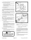
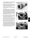
3. Clean wheel motor (1) and hydraulic connections.
Label all tube hose connections for reassembly pur-
poses. Put caps or plugs on any hydraulic lines or fittings
left open or exposed.
4. Disconnect tube connections (2 and 3) from hydrau-
lic fittings (5 and 6). On the left–hand wheel motor, also
disconnect hose connection (4) from hydraulic fitting (7).
Allow hydraulic oil to drain from tubes and hose into a
suitable container.
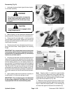
5. Support wheel motor (1). Remove four cap screws
(10) and lock nuts (11) from support frame (12). Remove
brake bracket (13), grass shield (14), and spacers (15).
Pull wheel motor from the support frame.
6. Remove hydraulic fittings (5 and 6) and O–ring from
the wheel motor (1). On the left–hand wheel motor, also
remove hydraulic fitting (7) from the wheel motor.
Front Wheel Installation (Fig. 30)
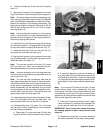
1. Place and support wheel motor (1) into the support
frame (12). Insert four cap screws (10) through the sup-
port frame and wheel motor.
2. Slide spacers (15), grass shield (14), and brake
bracket (13) onto the cap screws (10) and wheel motor
(1). Tighten lock nuts (11) onto cap screws.
3. Install hydraulic fittings (5 and 6) onto the wheel mo-
tor (1). On the left–hand wheel motor, also install hy-
draulic fitting (7) onto the wheel motor. Tighten hydraulic
fittings.
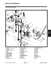
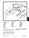
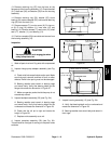
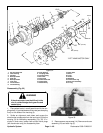
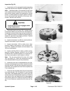
1. Wheel motor
2. Tube connection
3. Tube connection
4. Hose connection
5. Hydraulic fitting
6. Hydraulic fitting
7. Hydraulic fitting
8. O–ring
9. O–ring
10. Cap screw
11. Lock nut
12. Support frame
13. Brake bracket
14. Grass shield
15. Spacer
16. O–ring
17. O–ring
Figure 30
1
4
10
2
3
16
8
9 (LH)
7 (LH)
17 (LH)
6
16
14
15
13
11
12
5
4. Install tube connections (2 and 3) to hydraulic fit-
tings (5 and 6). On the left–hand motor, also ins hose
connection (4) to hydraulic fitting (7). Tighten connec-
tions.
5. Install wheel and brake to unit (see Repair section
of Chapter 6 – Wheels and Brakes).