Reelmaster 2300–D/2600–DHydraulic System Page 4 – 14
Mow
The reel motor drive pump is directly coupled to the the
traction pump which is driven directly by the engine
through the electric clutch. Taking its suction directly
from the reservoir, the reel motor drive pump supplies oil
flow to the hydraulic manifold block and to the reel mo-
tors.
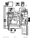
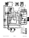
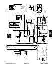
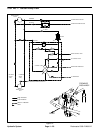
With the engine running, the clutch engaged, and the
cutting unit switch pushed in to the OFF position, oil
flows into inlet port (P1) and through deenergized sole-
noid valve (S1) bypassing the reel motors. Oil then flows
directly back to the reservoir through the oil cooler.
When the cutting unit switch is pulled out to the ON posi-
tion with the engine running and the clutch engaged, so-
lenoid valve (S1) is energized and shut, hydraulic
system pressure builds up, and flow is diverted to the
reel motors. Oil flow from port (P1) flows through the 11
position reel speed control valve. Flow across the speed
control valve is pressure compensated by the logic car-
tridge valve (LC1). The logic cartridge valve maintains
a pressure differential of 75 PSI (5.2 bar) across the
speed control valve. Any excess flow above what the
speed control valve is set for is bypassed to the reservoir
through the logic cartridge valve. With the backlap valve
(MD1) in the mow position, oil flows through the valve
and reel motors which are connected in series. Oil flows
through the right, center, and then left reel motor as it
turns the motors in the mow direction. The oil then re-
turns to the reservoir.
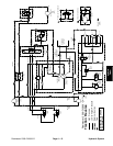
Relief valve (R1) limits system pressure and is set at
3000 PSI (207 bar). When the valve opens, oil is di-
verted back to the reservoir.
Backlapping operation is the same as mowing opera-
tion, except for the position of the backlap valve (MD1).
The backlap valve is in the backlap position allowing oil
flow through the left, center, and then right reel motor as
it turns the motors in the backlap direction.


