


Plan de raccordement
NOTICE: Toutes les dimensions sont nominales. L’espacement du montant est de
+1/8″ (3 mm)/-0. Mesurer soigneusement votre appareil avant d’en déterminer la
taille de son logement. Un calage entre le cadre du montant et l’appareil sanitaire
pourrait être nécessaire. Si un pare-feu est requis, les dimensions de raccordement
devront augmenter en fonction de l’épaisseur du matériau du pare-feu. Les
dimensions d’ouverture des montants doivent être mesurées vers le côté exposé du
matériau du mur . Les dimensions fournies dans le plan du raccordement sont
cruciales pour une bonne installation. Construire le cadre et la plomberie avec
exactitude.
Diagrama de instalación
AVISO: Todas las dimensiones son nominales. La tolerancia de abertura entre los
postes es de +1/8″ (3 mm)/-0. Mida con cuidado el producto antes de determinar las
dimensiones del encajonado. Quizás sea necesario colocar cuñas entre la estructura de
postes de madera y la unidad. Si se requiere una pared resistente al fuego, las
dimensiones del diagrama de instalación deberán aumentar según el grosor del
material resistente al fuego. Las dimensiones de abertura entre los postes se deben
medir por el lado expuesto del material de la pared. Las dimensiones del diagrama
de instalación son cruciales para una correcta instalación. Construya la estructura y
coloque las tuberías con precisión.
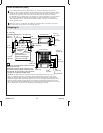
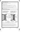
1. Construct the Framing
NOTE: Refer to the ″Roughing-In″ section for dimensions.
Framing Provisions
WARNING: Risk of product and property damage. The bath must be supported
by the subfloor.
The bath with apron must be attached to the studs on three sides.
A subfloor must be installed. The bath must be positioned to allow clearance for
drainage through the floor joists or slab and to allow convenient plumbing
installation.
Studs must be positioned roughly as shown in the ″Roughing-In″ section to
properly fasten the walls. Other stud locations are optional except for those which
must meet the load-bearing requirements of local building codes. Studs must also
allow for the installation of plumbing fittings.
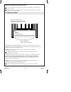
NOTE: If the wall surrounds will be installed to a masonry wall, make provisions for
plumbing connections. For the plumbing end wall, construct a separate frame wall a
minimum of 6″ (15.2 cm) from the masonry wall. For the remaining walls, use 2x2
furring strips to provide stud locations.
Ensure that the outer stud is positioned with the vertical wall flanges 31-1/4″ (79.4
cm) from the back wall. The outer edge of the stud should align with the edge of
the wall flange.
NOTICE: Accessories that require backing or support are not recommended for this
installation. Installing these accessories could void the warranty.
Sterling 11 1065823-2-C