ASSEMBLY
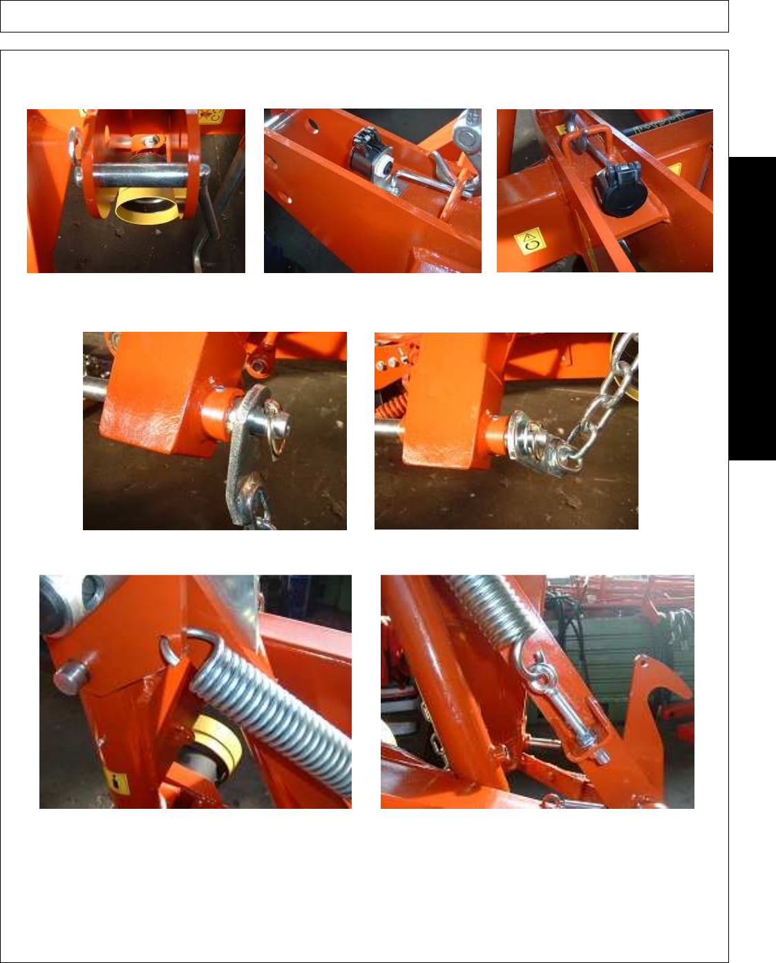
STEP 12. Insert the pin with grip of the three point and lock it with 1 pin “R” Ø
6. Mount the clutch support of the hydraulic hose
with 1 set hexagonal oval head screw M10x30 and one self-locking nut M 10.
STEP 13. Insert the pin for the linkage of the lifting device (on the right arm of the three point). Mount the chain support, 1
thick flat washer Ø25 and 8 mm 1 automatic pin. Connect the other end of the chain near the pin of the three point.
STEP 14. Connect the floatation device on one side to the hole shown in Picture 14.1 and on the other side to the threaded
rod. Insert 1 nut M12, 1 flat washer M12 and 1 self-locking nut M12 through the rod.
Picture 14.1 Picture 14.2
ASSEMBLY
AGM 52-62-72-82
10/10
Assembly Section 3-9
© 2010 Alamo Group Inc.


