ASSEMBLY
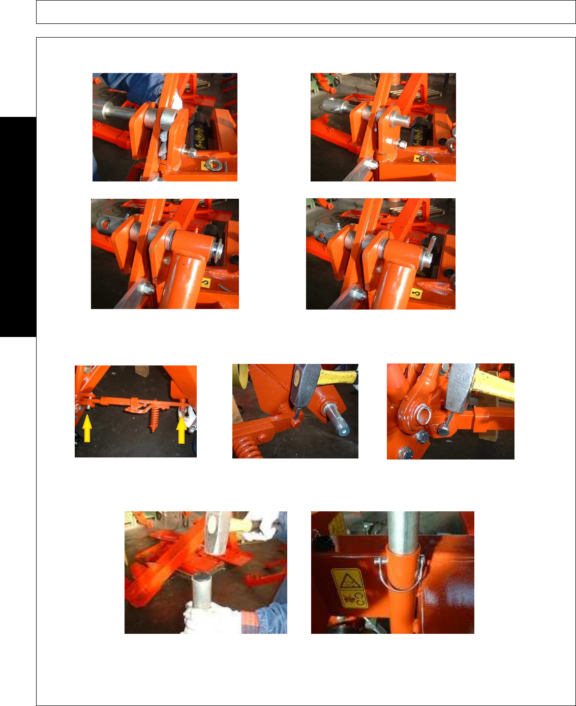
STEP 9. Connect the blade with the lever to the pin of the three point: insert the 1
st
shim, the blade with the lever and then the
2
nd
shim (Picture 9.1). Insert the 3
rd
shim (Picture 9.2), the hydraulic cylinder (Picture 9.3), n°2 washers and lock with 1 spring
plunger size=8x50 (Picture 9.4).
Picture 9.1 Picture 9.2
Picture 9.3 Picture 9.4
STEP 10. Mount the safety release device, insert the 25 mm pin (Picture 10.1) and lock it with 2 pins size=6x50 (Picture 10.2).
Lock the safety release device from the top with 1 pin size=8x50 (Picture 10.3).
Picture 10.1 Picture 10.2 Picture 10.3
STEP 11. Insert the black square plastic tap on the stand (Picture 11.1). Insert the stand on the pin on the frame bush, insert
1 flat washer Ø 25 and 1 8mm automatic pin (Picture 11.2).
Picture 11.1 Picture 11.2
ASSEMBLY
AGM 52-62-72-82
10/10
Assembly Section3-8
© 2010 Alamo Group Inc.


