


ASSEMBLY .......................................
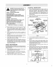
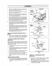
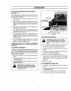
• Underneath the footrests of the tractor, remove hairpin
cotters and flat washers from the left and right hand
hanger pins and lay aside (see Fig. 7A)
• Remove hitch rod and hairpin cotter from front mounting
bracket and lay aside (see Fig 7B)
® Align holes in the mower deck hitch with the top set of
holes in the front mounting bracket and reinstall the hitch
rod and hairpin cotter (see Fig 7B),
e Place cutting height adjustment pedal in lowest position
by moving memory rod to position ! and pressing pedaf
latch to retease cutting height adjustment pedal NOTE:
Be sure left and right rear lift arms are to the inside of the
left and right deck liftbrackets (see Fig,, 7A).
e Lift deck slightly and flex left rear hanger pin inward to
snap hanger pin into left deck lift bracket stot Secure
hanger pin in place with flatwasher and hairpin cotter re-
moved earlier,
e Lift deck slightly and flex right rear hanger pin inwardto
snap hanger pin into right deck lift bracket slot. Secure
hanger pin in place with flatwasher and hairpin cotter
removed earlier (see Fig. 7A)
e Check mower deck leveling and adjustment as required
(See TO LEVEL MOWER DECK in SERVICE AND
ADJUSTMENTS section of this manual).
CHECK FOR PROPER POSITION OF ALL
BELTS
• .See figures shown for replacing motion and mower blade
drive belts in SERVICE AND ADJUSTMENTS
section of this manual Verify belts are routed correctly
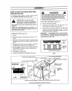
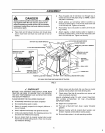
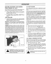
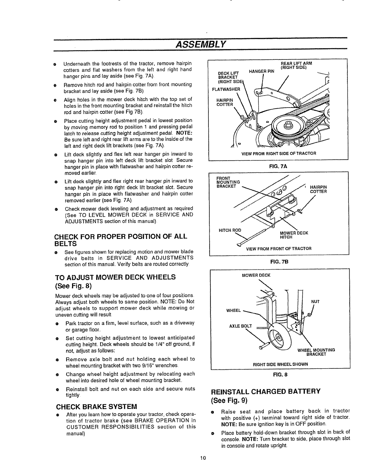
TO ADJUST MOWER DECK WHEELS
(See Fig. 8)
Mower deck wheels may be adjusted to one of four positions
Always adjust both wheels to same position. NOTE: Do Not
adjust wheels to support mower deck while mowing or
uneven cutting will result
• Park tractor on a firm, level surface, such as a driveway
or garage floor._
e Set cutting height adjustment to lowest anticipated
cutting heighL Deck wheels should be 1/4" off ground, if
not, adjust as follows:
• Remove axle bolt and nut holding each wheel to
wheel mounting bracket with two 9It6" wrenches
e Change wheel height adjustment by relocating each
whee! into desired hole of wheel mounting bracket.
e Reinsta!l bolt and nut on each side and secure nuts
tightly.
CHECK BRAKE SYSTEM
• After you learn how to operate your tractor, check opera-
tion of tractor brake (see BRAKE OPERATION in
CUSTOMER RESPONSIBILITIES section of this
manual)
DECK LIFT
BRACKET
FLATWASHER
HAIRPIN \_
COTTE R
HANGER PIN
REAR LIFT ARM
(RIGHT SIDE)
FRONT
MOUNTING
BRACKET
VIEW FROM RIGHT SIDE OF TRACTOR
FIG,,7A
HAIRPIN
COTTER
H_TCHROD
MOWER DECK
HITCH
VIEW FROM FROI_FrOF TRACTOR
FIG. 7B
MOWER DECK
WHEEL
NUT
AXLE BOLT
\
WHEELMOUNTING
BRACKET
RIGHTSIDEWHEELBHOWN
FIG, 8
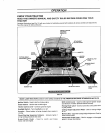
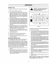
REINSTALL CHARGED BATTERY
(See Fig. 9)
• Raise seat and place battery back in tractor
with positive (+) terminal toward right side of tractor..
NOTE: Be sure ignition key is in OFF position.
• Place battery hold-down bracket through slot in back of
console. NOTE: Turn bracket to side, pface throughslot
inconsole and rotate upright
10