


19
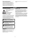
ENGINE/BLADE CONTROL
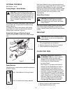
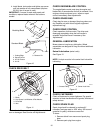
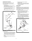
Engine Control must stop engine ignition, at 3/4”
to 1-1/4” from handlebar as control is released.
To check (Figure 16):
1. Start engine and slowly release Control until
engine stops firing.
2. Measure distance between handlebar and control
at the point that engine stopped firing.
3. Turn cable nuts at handlebar mount clockwise if
measurement is more than 1-1/4” or
counter-clockwise if measurement is less than
3/4”.
4. Turn nuts against mount to lock in position.
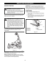
DRIVE BELT (Self propelled units)
To remove drive belt:
1. Position right hand rear wheel Height Adjustment
lever in first notch and left hand rear wheel Height
Adjustment lever in third notch. This provides
clearance between friction wheel and drive disk.
2. Remove belt from idler, drive disk and engine
pulley.
3. Pull belt through opening under mower pan and
over blade.
4. Check idler for free rotation of pulley and
movement of pivot.
5. Reinstall drive belt in reverse order. Be sure that
belt seats in pulley grooves with idler positioned
on back (flat) side of belt.
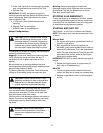
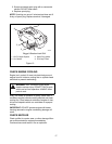
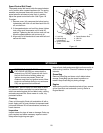
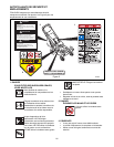
DRIVE WHEEL
See Figure 17.
When the Wheel Drive Control is squeezed toward the
handlebar the extension spring, located at the bottom
end of the traction cable, must start to extend when the
control is between 1-1/2" and 2" (3.8 and 5 cm) away
from the handlebar. To check:
1. Squeeze the Wheel Drive Control toward the
handlebar until the spring starts to open.
2. Measure the distance between the Wheel Drive
Control and handlebar at the handlebar
indentation.
3. To obtain the proper adjustment, turn the cable
nuts. Turn clockwise if the measurement is more
than 2"; counterclockwise if the measurement is
less than 1-1/2". Tighten the nuts against the
bracket to lock in position. If there is not enough
thread length for adjustment, the opposite end of
the cable can be adjusted.
1. Engine Control
2. Handlebar
3. Cable Nuts
4. Mount
Figure 16
3/4" - 1 1/4 "
OM0280
1
3
4
2
1. Traction Cable
2. Handlebar Indentation
3. Cable Nuts
4. Wheel Drive Control
Figure 17
1-1/2" to 2"
2
4
3
1
OM0290