


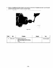
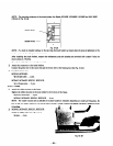

10-4 CONTROL BOX CHECK, DISASSEMBLY, and REASSEMBLY
lo-4- 1 CHECK
Check the wiring by removing the control box from the
frame and taking the top lid off.
10-4-2 DISASSEMBLY
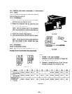
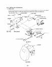
1) Remove the control box top lid, and the front panel
from the control box. (See Fig. 10-34.)
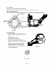
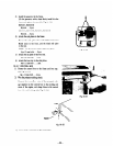
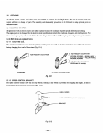
2) Remove the connectors from the control box, and
the wires from the connectors.
NOTE: Push the tenninal locks in #e connectors
with a long, pointed pin to unclock the terminals, and
remove them. (See Fig. 1 O-35.)
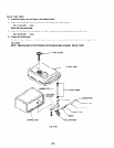
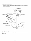
3) Remove the automatic voltage regulator.
4) After-disconnecting the wire from each part, remove
the parts.
NOTE: The DC fuse and the full po~rswitch have
their &es soldered to them. Unsolder their wires
first, and then remove them.
10-4-3 REASSEMBLY
Reverse the disassembly procedure.
NOTE: The wires are colored for identification of capacity
and gauge. Be wre to use the same wires as disconnected.
Fig. 70-34
9
PUSH
Fig. 1035
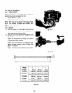
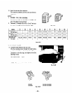
NOTES:
1. RGX505 - 1 lOV, 1aV; RGX505D.
Connectors are used for terminals 171 through (10)
only. 7rhe others are pin terminals
2 Terminals (1) through (61 are for a 2 mm2 wire and
terminals 171 through (1) for a 0.75 mm2 wire.
Fig. lo-36
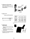
MODEL
@I@~@~@ 0 @ 0 @ @I @
RGX305.405
220.230.24OV
BROWN ORANGE 1 WHITE ! RED - 3 -
BROWN
GREEN
WHITE RED
I
RGX505
220,230,24OV i
BROWN : ORANGE ! WHITE
RED
WHITE
RED ’ BROWN GREEN WHITE RED
I
RGX305D. 405D
I
RGX305.405
’ BROWN ’ ORANGE WHITE i RED
YELLOW i BLACK BROWN GREEN
WHITE
RED
110,120v
I
1
Table 10-6
-58-