10-3-3 STATOR
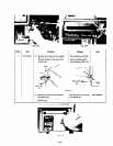
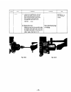
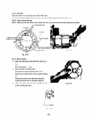
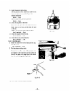
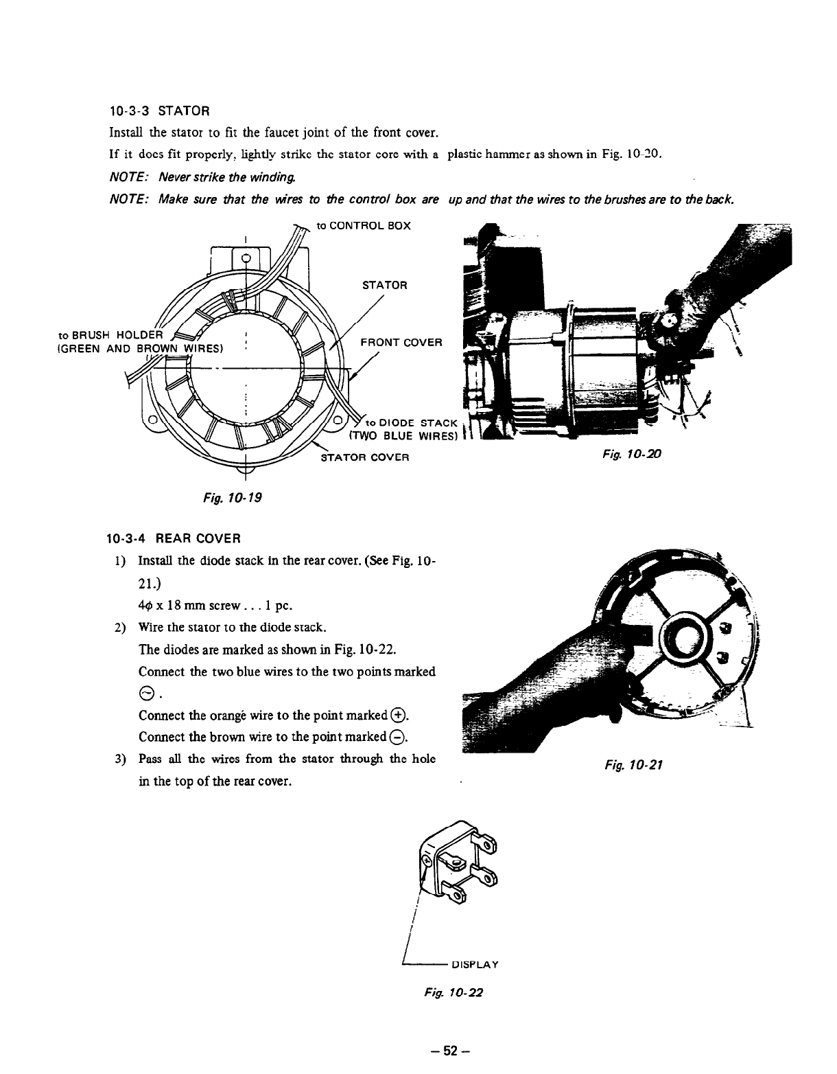
Install the stator to fit the faucet joint of the front cover.
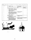
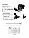
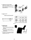
If it does fit properly, lightly strike the stator core with a plastic hammer as shown in Fig. 10-20.
NOTE: Never strike the winding.
NOTE: Make sure that the mares to tie control box are up and that the wires to the brushes are to the back.
h to CONTROL BOX
toBRUSH HO
(GREEN AND
FRONT COVER
o DIODE STACK
0 BLUE WIRES)
ATOR COVER
Fig. lo-19
10-3-4 REAR COVER
1)
2)
3)
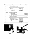
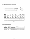
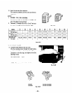
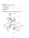
Install the diode stack in the rear cover. (See Fig. lo-
21.)
40 x 18 mm screw . . . 1 pc.
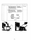
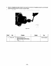
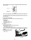
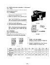
Wire the stator to the diode stack.
The diodes are marked as shown in Fig. 10-22.
Connect the two blue wires to the two points marked
0.
Connect the orange wire to the point marked 0.
Connect the brown wire to the point marked 0.
Pass all the wires from the stator through the hole
in the top of the rear cover.
Fig. lo-20
Fig. lo-21
I
L-
DISPLAY
Fig. lo-22
- 52 -


