


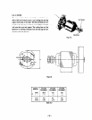
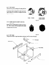
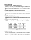

5-3-4 FULL POWER SWITCH
The
dual
voltage
type has a full power switch to produce the rated output from a single 11OV or 120V receptacle. The full
power switch operates as described below. (The full power switch for 12OV/24OV is described as the construction of both
full power switches for 12OV/24OV and 1 lOV/22OVis same.
240V
I
i-J?-; i
7
Fig. 5-18 Fig. 5- 19
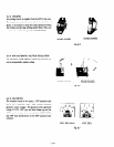
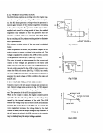
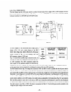
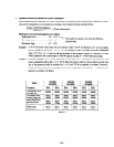
A circuit diagram of the conventional dual voltage type is
Switch
LOW VOLTAGE HIGH VOLTAGE
shown in Fig. 5 - 18, and a circuit diagram of the RGX
RECEPTACLE RECEPTACLE
I
Series’ dual voltage type which is fitted with a full power
switch is shown in Fig. 5-19. AC winding s MC1 and
MC2 generate a voltage of 120V each.
Fig. 5 - 18 shows MC1 and MC2 kept connected in series. In
this case, an output can be generated from either the 240V
’
I
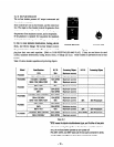
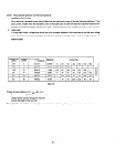
Table 5-5
or 120V receptacle. The 240V receeptacle outputs the
rated output (or the maximum output in a short-time op-
eration), but one 120V receptacle can output only one half of the rated output. Since two 120V receptacles are provid-
ed: the rated output can be outputted by combining the outputs of the two 12OV receptacles.
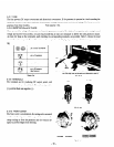
The RGX Series shown in Fig. 5-19 changes the connection of MC1 and MC2 to series or parallel with the full power switch.
When the full power switch is shifted to the 12OV/24OV postion, the switch is up as indicated by the solid line in Fig. 5-19,
and connects MC 1 and MC2 in series as shown in Fig. 5-l 8. In this case, voltages up to the rated level can be outputted from
Receptacle 3, and voltages up to one half (12OV) of the rated voltage from Receptacle 1 and Receptacle 2. (If the rated cur-
rent is over 30A at 12OV, up to 15A can be outputted from Receptacle 1 as the combined output of the two.) When the full
power switch is shifted to the 120V position, the switch is down as indicated by the broken line in Fig. 5-19, and connects
MC1 and MC2 parallel to each other. In this case, no 240V can be outputted, and Receptacle 3 cannot be used. Receptacle
2, which outputs 120V can generate up to the rated power; and Receptacle 1 can output up to 15A in total (or up to 30A if
the rated current is over 30A at 120V). The above is summarized in Table 5-5. Use the full power switch as suitable to the
voltage and input ratings of the electric devices.
- 24 -