


CONTENTS
Section
Title Page
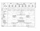
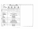
1. SPECIFICATIONS
..........................................
1
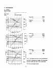
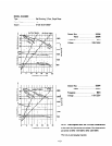
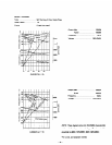
2. PERFORMANCE
...........................................
3
2-1
Model RGX305
......................................
3
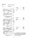
2-2
Model RGX305D
.....................................
4
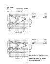
2-3
Model RGX405
......................................
5
2-4
Model RGX405D
.....................................
6
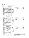
2-5
Model RGX505
......................................
7
2-6
Model RGX505D
.....................................
8
3. FEATURES
..............................................
9
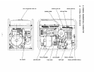
4. GENERAL DESCRIPTION of GENERATOR
........................
11
4 - 1
External View of Generator
..............................
11
4-2 Panel A
............................................
12
4-3 Panel B
............................................
13
5. CONSTRUCTION and FUNCTION
...............................
14
5-1
Construction
........................................
14
5-2 Function ...........................................
15
5-3
Description of Generator Operation
.........................
21
5-4
Change of Engine Parts
.................................
25
6. SAFETY PRECAUTION
......................................
28
7. APPLICABLE RANGE of GENERATOR
...........................
29
8. MEASURING PROCEDURE
...................................
32
8-1
Meters ............................................
32
8-2
AC Output Measuring
..................................
34
8-3
DC Output Measuring
..................................
34
8-4
Insulation Resistance Measuring
...........................
34
9. CHECKING FUNCTIONAL MEMBERS.
...........................
36
9 - 1
Stator Assembly
......................................
36
9-2
Rotor Assembly
......................................
37
9-3
Brushes. ...........................................
38
9-4
AVR (Automatic Voltage Regulator)
........................
38
9-5
No-Fuse Breaker and Fuse Holder
..........................
40
9-6
Receptacle and AC Plug
.................................
41
9-7
Voltmeters
.........................................
41
9-8
Diode Stack Assembly
..................................
41
9-9
Primary Exciting Circuit
................................
42
10. DISASSEMBLY and REASSEMBLY
..............................
43
10 - 1
Preparations and Suggestions
.............................
43
10-2
How to Disassemble
...................................
43
10-3
How to Reassemble.
...................................
51
10-4
Control Box Disassembly and Reassembly
.....................
58
11. TROUBLE-SHOOTING
.......................................
59
12. OPTlON
.................................................
63
12 - 1
Electric Starter.
......................................
63
12-2 Caster
.............................................
68
13. CIRCUIT DIAGRAM
........................................
69