


9-4
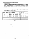
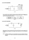
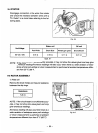
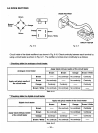
STATOR
Disengage connectors
on
the wires from stator
and check the resistance between wires with a
“Dr.
Robin”
or
a circuit tester referring to the
fol-.
lowing table.
Fig.
44
r
Stator
coil
DC
coil
Hz-Voltage
Red-White
BrownBrown
WhiteLight green
Black-Blue
60-1 20
/
240
0.61
SZ
0.11
D
0.16
SZ
0.16
SZ
NOTE
:
If the circuit tester is not sufficiently accurate, it may not show the values given and may give
erroneous readings. Erroneous readings will also occur when there is
a
wide variation
of
resis-
tance among
mil
windings or when measurement is performed at ambient temperatures differ-
ent from
20
OC
(68
OF).
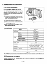
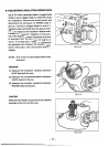
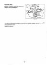
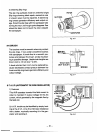
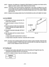
9-5
ROTOR
ASSEMBLY
I)
Field coil
Remove
the
brush holder
and
measure resistance
between the slip rings.
Resistance
NOTE
:
If the circuit tester is not sMicientIy accu-
rate,
it
may
not show the values given and may
give erroneous readings.
Erroneous reading will also occur when there is a
wide variation
of
resistance among coil windings
or when measurement is performed at ambient
temperatures different from from
20
’
C
(68
’
F).
-
‘SUP
UNG
Fig.
9-5
-
30-