


53
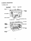
DESCRIPTION
Of
GENERATOR
OPERATION
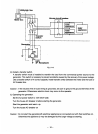
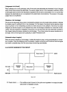
5-3-1
PRIMARY
EXCITING
ACTION
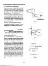
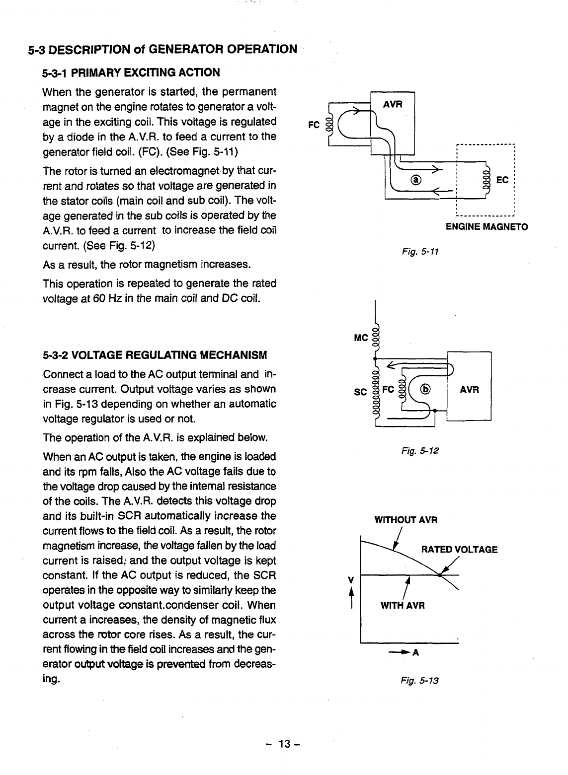
When the generator is started, the permanent
magnet on the engine rotates to generator a volt-
age in the exciting coil. This voltage is regulated
by
a
diode in the A.V.R. to feed a current to the
generator field coil. (FC). (See Fig.
5-11)
The rotor is turned an electromagnet by that cur-
rent and rotates
so
that voltage are generated in
the stator coils (main coil and sub coil). The volt-
age generated in the sub coils is operated
by
the
A.V.R. to feed a current to increase the field coil
current. (See Fig.
5-12)
As a result, the rotor magnetism increases.
This operation is repeated to generate the rated
voltage at
60
Hz
in the main coil and
DC
coil.
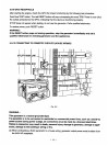
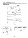
5-3-2
VOLTAGE REGULATING MECHANISM
Connect a load to the AC output terminal and in-
crease current. Output voltage varies as shown
in Fig.
5-13
depending on whether an automatic
voltage regulator is used or not.
The operation
of
the A.V.R. is explained below.
When an AC output is taken, the engine is loaded
and its rpm falls, Also the AC voltage fails due to
the voltage drop caused by the internal resistance
of the coils. The
A.V.R.
detects this voltage drop
and its built-in SCR automatically increase the
current flows to the field coil. As a result, the rotor
magnetism increase, the voltage fallen by the load
current is raised: and the output voltage is kept
constant. If the AC output
is
reduced, the SCR
operates in the opposite way to similarly keep the
output voltage constant.co,ndenser coil. When
current a increases, the density of magnetic flux
across the rotor core rises. As a result, the cur-
rent flowing
in
the field
coil
increases and the gen-
erator
output
voltage
is
prevented from decreas-
ing.
FC
n
EC
i
L""""""-J
ENGINE
MAGNETO
Fig.
5-
11
Fig.
5-12
WITHOUT AVR
RATED VOLTAGE
v
I
4A
Fig.
5-
13
-
13-