


802BT/802R Video Test Generator User Guide 703
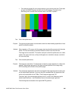
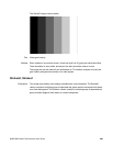
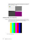
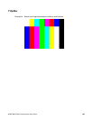
Purpose This general purpose pattern can be used to check the video handling capabilities of most
parts of a television system.
Method When viewed on a TV screen, all of the colors should be correct and in the order shown.
The hue and intensity of each bar should be uniform over the entire bar.
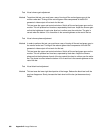
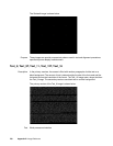
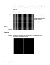
The image can be used with a TV waveform analyzer to check the performance of a video
system. Individual scan lines of each image, as they would appear on a waveform
analyzer, are shown on the following page.
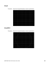
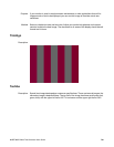
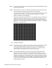
The image is quite effective when used with a TV vectorscope to see how a video system
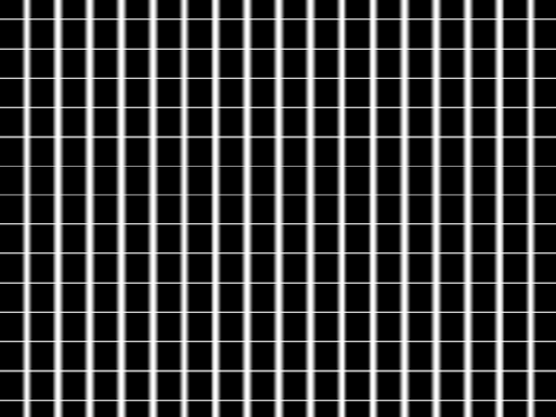
handles an encoded color signal.The image consists of a white crosshatch on a black
background. The lines form square boxes when the display’s active video area has a 4:3
aspect ratio. The vertical lines are made using sine-squared (2 T) pulses (T = 125 nSec for
NTSC and T = 100 nSec for PAL).
Test Convergence adjustment
Purpose To accurately produce an image on a color monitor, the three electron beams in the CRT
must meet (converge) at the same location at the same time. Lines displayed on a
mis-converged monitor will appear as several multi-colored lines, and the transitions
between different colored areas will contain “fringes” of other colors.
Method The convergence adjustments of most color monitors can be divided into two main
categories. The first set of adjustments, usually called “Static Convergence,” calls for
aligning the three beams in the center of the display. This method involves turning on all
three guns and adjusting the various magnets on the convergence assembly to produce
all white lines and dots in the center of the display. The convergence assembly is located
on the neck of the CRT. Different monitors and CRT types may each require their own
magnet adjustment sequence.