


124 Chapter 8 Analyzing Digital Sources and Cables
• Select MANUAL to define specific patch settings.
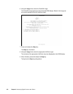
10. To define specific settings for delta error patch (width, height, and position), follow these
steps:
a. Using the Format knob, select the Width, Height, X, or Y field.
Note: If you selected AUTO in the Parameters field and the HDMI/DVI signal source is
internal (Auto Based On field set to CURRENT), the Width and Height fields are not
selectable. Similarly, if you selected AUTO in the Parameters field and the HDMI/DVI
signal source is external (Auto Based On field set to MEASURE), the Width and Height
fields are set when measuring the external signal’s timing parameters (see “Setting up
analyzer to measure timing” on page 114).
b. Set the parameter (in decimal) using the cursor (displayed under a digit in the field)
to select the appropriate value as follows:
• To move the cursor between digits, press the R and G keys.
• To select a number for a digit, turn the Image knob.
c. Repeat these steps until each parameter is defined.
11. Using the Format knob, select the Reference Frame field.
12. Using the Image knob, specify the method used to compare the patch within different
frames as follows:
• Select FIRST to use the first field as the reference for comparison with other
patches in other frames.
• Select PAIRS to set the comparison to be performed in each two successive
frames.
13. Using the Format knob, select the Frames Compared field.
14. Specify the number of frames to be compared with the patch dimensions using the
cursor (displayed under a digit in the field) to select the appropriate value as follows:
• To move the cursor between digits, press the R and G keys.
• To select a number for a digit, turn the Image knob.
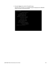
15. Press and release the Step key to save the currently displayed parameters.
The light on the Step key extinguishes, and the settings are implemented for Analyzer
mode operation.