


802BT/802R Video Test Generator User Guide 197
Operating special sync for probe pulse
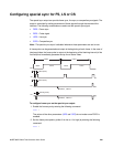
The probe feature is used in connection with a programmable probe pulse that is available
on the S/S BNC. This pulse is most often used to trigger an oscilloscope or synchronize an
inspection camera. The probe feature allows you to position the leading edge of the probe
pulse anywhere within the video frame. This feature greatly facilitates troubleshooting by
enabling you to focus on specific video signal problems occurring anywhere in the video
signal.
Configuring the probe feature involves positioning the probe pulse in the desired location
on the video frame. You can do this either through the front panel or the command line
interface. The front panel display is most convenient if you are near the generator and not
using a computer or terminal. You can control the generator through the command line
interface either locally or remotely through the serial connection.
Front panel controls and indicators
To use the probe feature begin by first activating the probe feature through the generator
keys, and then positioning the pulse in the desired location by turning the Format knob
(horizontal position) and the Image knob (vertical position). The current position of the
pulse is shown on the LCD.
Probe coordinate numbering
Unlike ITU and SMPTE standards, Quantum Data standards count pixels, lines, and
coordinates beginning with the number zero (not one) to improve the mapping between
video signal specifications and modern computer graphics coordinates. The television
standards are accounted for by suppressing any half-active line that appears in an
equalizing interval and lengthening (to a full line) any half-active line that begins in the
active portion of a field. Vertical counting always begins with the leading edge of blanking
of the first field (not vertical sync). The first field is always defined as the field that includes
the top line of the displayed picture (Y:0). This definition is always true whether the total
number of active lines is odd or even.
With interlaced scanning, lines continue to be numbered sequentially throughout the
frame, beginning with the leading edge of blanking of the first field. Therefore, the first two
lines of blanking in the first field are numbered L:0 followed by L:1. If you have 525 total
lines and 486 of those are active, for example, the first two (blank) lines of the second field
would be numbered L:262 and L:263. The Y position continues to follow the visual order of
lines going from the top to the bottom of the screen. If the last line of blanking in the first
field is L:18, then L:19 corresponds to Y:0, L:20 to Y:2, L:21 to Y:4 and so on. In the
second field, L:282 would correspond to Y:1, L:283 to Y:3, L:284 to Y:5 and so on.