


694 Appendix B Image Reference
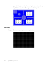
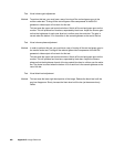
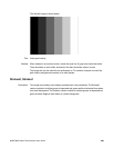
Method The horizontal 1 on - 1 off stripes in the resolution boxes should not have objectionable
flicker when shown with an interlaced format. Excessive flicker indicates that the
combination of the display’s CRT persistence and frame scan rate is below the persistence
time of the human eye.
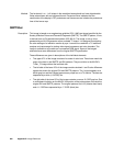
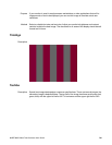
SMPTEbar
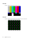
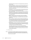
Description This image is based on an engineering guideline (EG1-1990) test signal specified by the
Society of Motion Picture and Television Engineers (SMPTE). The SMPTE pattern, in turn,
is derived from an EIA standard test pattern (RS-189-A). The image, is set up to be
generated by an 801GX generator as an encoded TV output. It is designed for adjusting
the color settings of a television monitor by eye. It can also be used with a TV waveform
analyzer and vectorscope for testing video signal processors and color decoders. The
image is available on all models as a component RGB signal. Some of the image’s
elements have some differences from the original SMPTE specification.
These differences are given in descriptions of the individual elements.
• The upper 67% of the image consists of a series of color bars. These bars match the
order of the bars in the SMPTE and EIA patterns. They are similar to the 801GX’s
TVBar_75 image without the last black bar.
• The left side of the lower 25% of the image contains isolated -I and Q color difference
signals that match the original EIA and SMPTE patterns. The -I signal appears as a
bluish-gray bar and the Q signal appears as a purple bar on a TV monitor. The bars are
separated by a white (+100 IRE) bar.
• The right side of the lower 25% of the image contains a narrow 12.5 IRE gray bar. Due
to a hardware limitation on the 801GX, this portion of the pattern does not match the
original EIA and SMPTE patterns. The original patterns had +3.5 (blacker than black)
and +11.5 IRE bars separated by a +7.5 IRE (black) bar.