


15
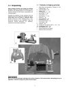
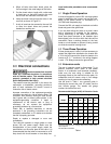
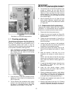
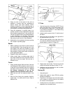
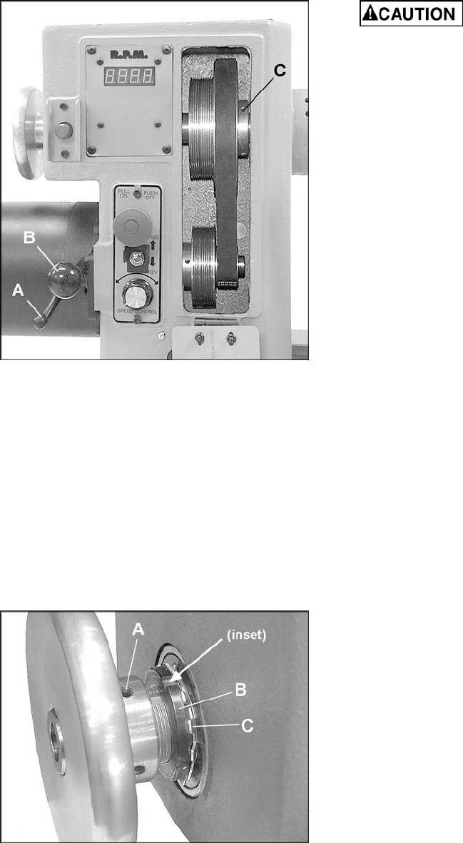
Figure 22
Belt shown in LOW speed range position
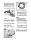
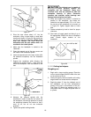
9.11 Checking spindle play
The spindle bearing has been set at the factory for
general turning applications. There should be no
"end play" or looseness along the spindle’s axis. If
any looseness should ever occur, it may be
rectified by carefully tightening the bearing lock nut
on the spindle, as follows. (See Figure 23).
1. Use a screwdriver to carefully bend back any
tabs on the tabbed lock washer (C, Figure 23)
that interfere with the insets on the bearing
lock nut (B, Figure 23).
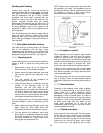
Figure 23
2. Place the end of a flat head screwdriver down
against one of the insets of the bearing lock
nut (B, Figure 23).
3. Tap the handle of the screwdriver with a mallet
so that it turns the bearing lock nut (B, Figure
23) tighter in a clockwise direction. Rotate the
bearing lock nut only about 1/16” at a time.
Do not over tighten the bearing
lock nut or the spindle bearings will overheat.
4. The bearing lock nut should be tightened just
enough to remove the end play and the
spindle should still rotate very freely. Run the
lathe for a time, and check for heat from the
spindle bearings. If the bearings are running
hot, the bearing lock nut is too tight and should
be loosened slightly.
5. After the bearing lock nut (B, Figure 23) has
been properly adjusted, carefully bend back
into place any tabs on the tabbed lock washer
(C, Figure 23).
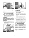
9.12 Sheave/drive belt replacement
Replacing the spindle sheave can be a difficult
procedure; it is recommended that the headstock
be taken to an authorized service center for this.
1. Disconnect Lathe from power source.
2. Loosen the pivot lock handle (A, Figure 22)
and lift up the tension handle (B, Figure 22) to
raise the motor.
3. Tighten the pivot lock handle (A, Figure 22) to
hold the motor in the raised position. Slip the
belt off the pulleys.
4. Loosen the two set screws on the handwheel
(A, Figure 23) with a hex wrench, and pull the
handwheel off the headstock spindle.
5. Loosen and remove the bearing lock nut (B,
Figure 23) and tabbed lock washer (C, Figure
23).
6. Slide the spindle a little way out of the
headstock, just enough to remove sheave or
belt.
NOTE: You may have to tap the end of the
spindle with a wood block to move it. (Do NOT
use a steel face hammer directly against the
spindle.)
7. If replacing the spindle sheave, loosen the two
set screws (C, Figure 22), and slide the
sheave off the spindle.
8. Install the new spindle sheave, loosely
securing the two set screws. Make sure the
sheave is oriented properly.
9. Slide the spindle back into place, install tabbed
lock washer (C, Figure 23), and bearing lock
nut (B, Figure 23). Check for any spindle play
at this point (See “Checking Spindle Play”).
10. Re-install the handwheel and tighten the set
screws (A, Figure 23).
11. Align the new sheave (see sect. 9.10, Sheave
and Belt Alignment) then tighten the two set
screws (C, Figure 23) securely on the sheave.