


12
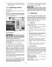
9.0 Adjustments
9.1 Headstock and tailstock
movement
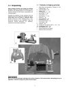
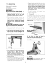
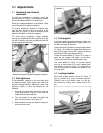
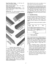
To slide the headstock or tailstock, swing the
locking handle (A, Figure 13) backward or forward
until the headstock/tailstock can slide freely.
When the headstock/tailstock is positioned, rotate
the locking handle to tighten it securely.
To remove headstock, tailstock or toolrest base
from the bed, unscrew and remove either of the
stop bolts (B, Figure 13). After re-mounting these
items on the Lathe, re-insert the stop bolt.
For most turning operations, except outboard
turning, the headstock should be positioned at the
left end of the bed, and only the tailstock moved to
accommodate the workpiece.
Figure 13
(shown with optional spindle comparator bracket)
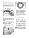
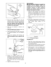
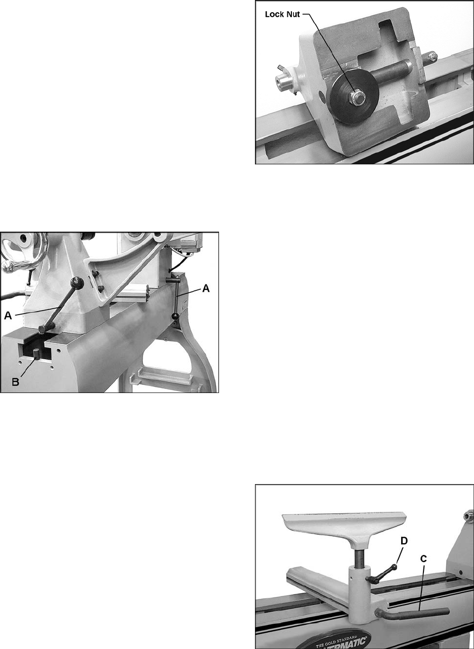
9.2 Cam tightness
If the headstock, tailstock or tool rest base does
not tighten properly down against the Lathe bed
when the locking handle is tightened, it may need
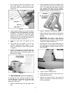
adjusting. Figure 14 uses the tailstock as the
example:
1. Unscrew and remove the stop bolt on the end
of the lathe bed (B, Figure 13) and slide the
tailstock off the end of the bed.
2. Turn the tailstock on its side, and tighten the
lock nut with a wrench. See Figure 14.
3. Mount tailstock on bed and insert the stop bolt
at the end of the bed.
Figure 14
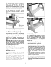
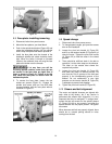
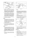
9.3 Tool support
A 14” tool support is provided with your Lathe. It is
designed to allow adjustment for height, position on
the bed, and angle to the work.
Loosen the locking handle on the tool support base
(C, Figure 15) to slide the support base forward or
back, and to angle it to the bed. Tighten the locking
handle firmly before operating the Lathe.
Loosen the small handle (D, Figure 15) to raise or
lower the tool support and angle it to the work.
Tighten the handle before operating the Lathe.
The small handle (D, Figure 15) can be inserted
into one of three holes on the tool support base.
The position shown in Figure 15 is preferred so
that the locking handle contacts the groove in the
tool rest shaft.
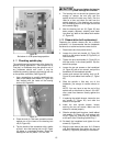
9.4 Locking handles
Each small locking handle such as D, Figure 15
can be rotated to a more convenient position.
Simply lift up on the handle, rotate it on the pin,
then release it, making sure it seats itself on the
pin.
Figure 15