20
A keylight (LED) is associated with each key or button. This can light when the associated function is
active. In some conditions, the keylight can blink to indicate an action status.
The keypad key functions can be remapped to any of the primary function keys using the PC programming
software. It is suggested that the blank keypad (located at the back of this manual) be completed if the
keypad key functions are changed.
8.7.1 Standard Keycap Configuration
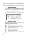
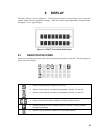
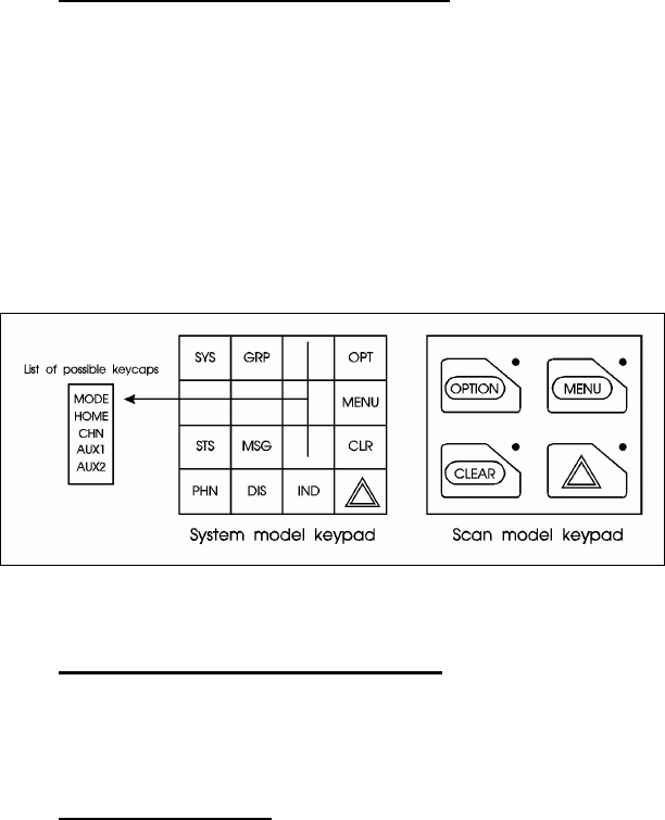
The Standard keycap package for the System radio includes five (5) labeled keycaps (MODE,
HOME, CHN, AUX1 and AUX2) and six (6) blank keycaps, which can be placed on any of the
five key locations (numbers 3-6 and 9) shown in
Figure 8-3. The keycap represents the primary
function programmed for that key location. See Section
8.7.3 for a description of the primary
function associated with these five (5) keycaps.
The standard keycap package for the Scan radio includes five (5) labeled keycaps [MENU,
CLEAR, SELECT, EMERGENCY
E or “E,” and OPTION] and five (5) blank keycaps,
which can be placed on any of the four (4) keypad keys. The keycap represents the primary
function programmed for that key location.
Figure 8-3: Standard M7100
IP
Keycaps Configuration
8.7.2 Optional Keycap Configuration
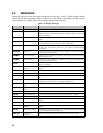
The optional keycap package for the System radio includes sixty (60) additional keycaps (shown
in Section
8.7.3), which can be placed on any key location desired. Keep in mind, the keycap
represents the primary function programmed for that key location.
8.7.3 Key Descriptions
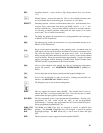
MODE This key is used to enter the Conventional System selection mode.
HOME This key returns the radio to the Home System/Group where it is programmed.
CHN This key is used to enter the Channel select mode.
AUX1 & 2
These keys are used to control output 1 or 2. Their definition is PC programmable.
S This key is used to enter the System select mode.
g This key is used to enter the Group select mode.
o
or
O
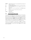
The “OPT” or “OPTION” key is used to toggle a PC programmable feature ON
and OFF.


