


DCA85USJ2 60 HZ GENERATOR • OPERATION AND PARTS MANUAL — REV. #1 (03/22/11) — PAGE 45
OUTPUT TERMINAL PANEL CONNECTIONS
3Ø-480/277V UVWO Terminal Output Voltages
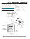
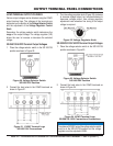
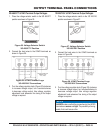
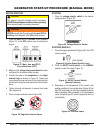
1. Place the voltage selector switch in the 3Ø 480/277
position as shown in Figure 25.
Figure 25. Voltage Selector Switch
3Ø-480/277V Position
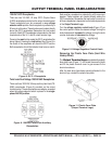
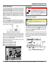
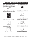
2. Connect the load wires to the UVWO terminals as
shown in Figure 26.
Figure 26. UVWO Terminal Lugs
3Ø-440/254V Connections
3. Turn the voltage regulator knob (Figure 22) clockwise
to increase voltage output, turn counterclockwise
to decrease voltage output. Use voltage regulator
adjustment knob whenever fi ne tuning of the output
voltage is required.
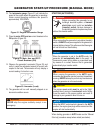
1Ø-240/120V UVWO Terminal Output Voltages
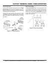
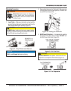
1. Place the voltage selector switch in the 1Ø 240/120
position as shown in Figure 27.
Figure 27. Voltage Selector Switch
1Ø-240/120V Position
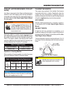
2. Connect the load wires to the UVWO terminals as
shown in Figure 28.
Figure 28. UVWO Terminal Lugs
1Ø-200/100V Connections
3. Turn the voltage regulator knob (Figure 22) clockwise
to increase voltage output, turn counterclockwise to
decrease voltage output. Use voltage regulator
adjustment knob whenever fi ne tuning of the output
voltage is required.
NOTICE
ALWAYS make sure that the connections to the UVWO
terminals are secure and tight. The possibility of arcing
exists, that could cause a fi re.