


PAGE 44 — DCA85USJ2 60 HZ GENERATOR • OPERATION AND PARTS MANUAL — REV. #1 (03/22/11)
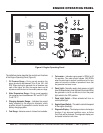
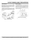
OUTPUT TERMINAL PANEL CONNECTIONS
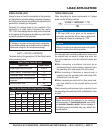
UVWO TERMINAL OUTPUT VOLTAGES
Various output voltages can be obtained using the UVWO
output terminal lugs. The voltages at the terminals are
dependent on the position of the Voltage Selector Switch
and the adjustment of the Voltage Regulator Control
Knob.
Remember the voltage selector switch determines the
range of the output voltage. The voltage regulator (VR)
allows the user to increase or decrease the selected
voltage.
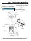
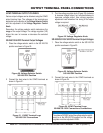
3Ø-240/139 UVWO Terminal Output Voltages
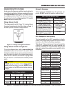
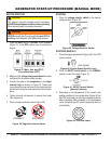
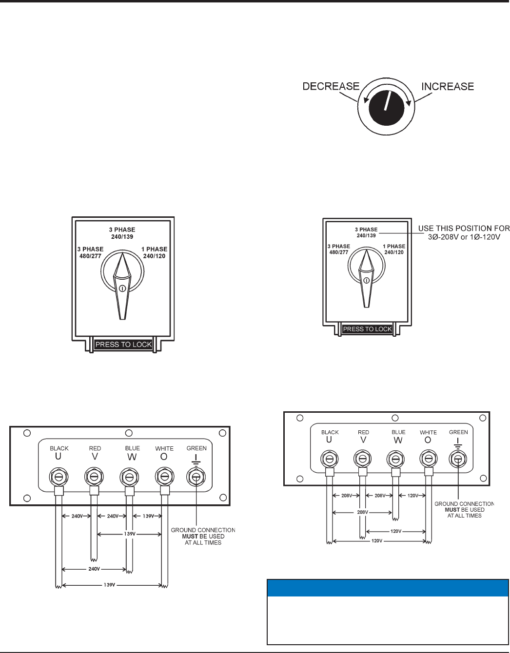
1. Place the voltage selector switch in the 3Ø 240/139
position as shown in Figure 20.
Figure 20. Voltage Selector Switch
3Ø-240/139V Position
2. Connect the load wires to the UVWO terminals as
shown in Figure 21.
Figure 21. UVWO Terminal Lugs
3Ø-240/139V Connections
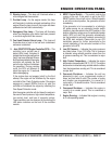
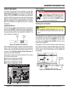
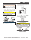
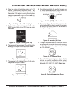
3. Turn the voltage regulator knob (Figure 22) clockwise
to increase voltage output, turn counterclockwise to
decrease voltage output. Use voltage regulator
adjustment knob whenever fi ne tuning of the output
voltage is required.
Figure 22. Voltage Regulator Knob
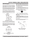
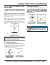
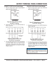
3Ø-208V/1Ø-120V UVWO Terminal Output Voltages
1. Place the voltage selector switch in the 3Ø 240/139
position as shown in Figure 23.
Figure 23. Voltage Selector Switch
3Ø-240/139V Position
2. Connect the load wires to the UVWO terminals as
shown in Figure 24.
Figure 24. UVWO Terminal Lugs
3Ø-208/1Ø-120V Connections Connections
NOTICE
To achieve a 3Ø 208V output the voltage selector switch
must be in the 3Ø-240/139 position and the voltage
regulator must be adjusted to 208V..