


10 se c t i O n 4 — as s e M b l y & in s t a l l a t i O n
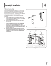
Assemble Mounting Brackets
To assemble the universal mounting assembly, locate the
mounting assembly pack and follow these steps:
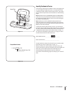
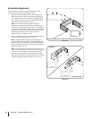
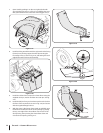
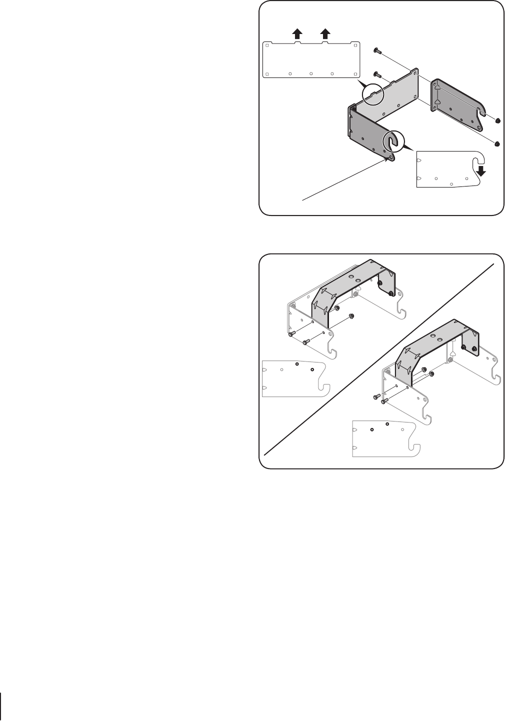
Attach the two hitch side brackets to the universal rear 1.
attachment bracket using four hex bolts and flange lock
nuts. With the hooks on the hitch side brackets pointing
down, the tabs on the universal rear attachment bracket
should be pointing upwards. See Fig. 4-3.
Note: This universal mounting bracket assembly is
designed to work with other available attachments, such
as a weight kit used in conjunction with the snow blade or
snow thrower attachment. Utilize the contact information
on page 2, or contact the retailer in which you purchased
this equipment, to find out more about available
attachments for your specific tractor.
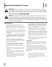
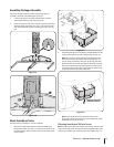
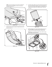
Flip over assembly and mount the hitch support bracket 2.
to the mounting assembly as seen in Fig. 4-4.
Note: It might be easier during the mounting stage to
leave this hardware only finger tight to facilitate lining up
the hitch hole for the clevis pin. You will be instructed to
tighten this later in this manual if you chose to only finger
tighten this hardware now.
Note: The holes closest to the mounting hooks are to be
used for all 700 model series machines, while the two holes
closest to the cross mount are for all other models. The
hitch support bracket will need to be flipped to enable
alignment of the proper holes depending on the model of
machine this bagger is being installed on. See Fig. 4-4.
For all other models
For 700 models
Side View
Side View
Figure 4-3
Figure 4-4
Hole provided for clevis pins for all 700 series mountings